Level Rail Installaon (Connued)
DekPro™ Presge Aluminum Rail System
Level Railing Installaon Instrucons
Measure in 1/4” and cut to allow for bracket wall thickness
* DekPro™ boxes come
with a cardboard rail comb
to help align and speed up
rail kit assemblies
Kit Includes:
1 - Top Rail (Baluster connectors installed)
1 - Boom Rail (Baluster connectors installed)
2 - Boom Rail Brackets
2 - Top Rail Brackets
1 - Foot Block Rail Support Kit
Aluminum Balusters
• 15 Balusters with 6’ kit
• 21 Balusters with 8’ kit
(All hardware is included to complete rail kit assembly)
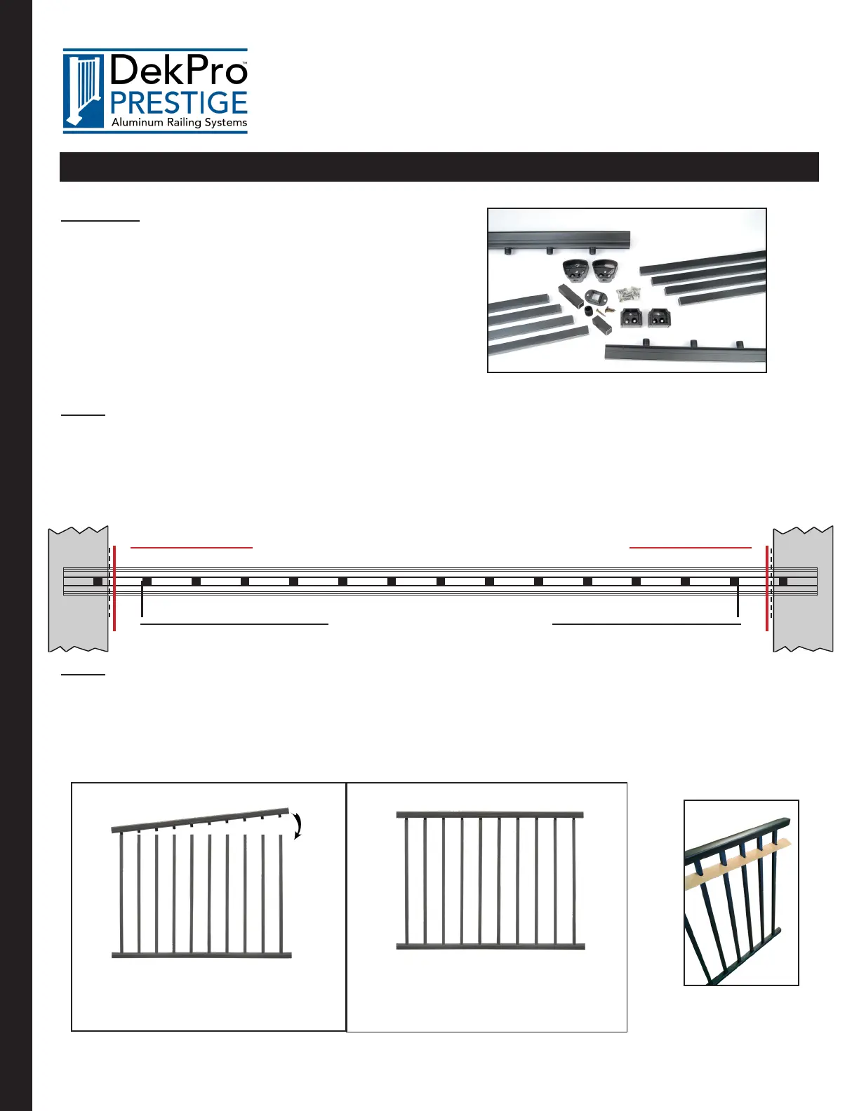
Step 4: Cut Rails to Size
• Measure distance from post to post and deduct 1/4” from each end of rail.
(1/4” deducon accounts for rail bracket wall thickness)
• Measure boom rail ensuring equal and maximum spacing from end of rail to the rst baluster on both
ends of the boom rail.
• Cut boom rail with a high tooth count carbide blade.
• Repeat previous steps when measuring and cung the top rail.
Step 5: Assemble Rail Kit
A.) Insert balusters onto the baluster connectors of the boom rail. Insert rst two balusters from one end of
top rail and progressively work your way to the other end to aach top rail to balusters (rail packaging comes with
a cardboard rail comb to help align and speed up rail kit assembly). B.) Aer all connectors are engaged with the bal-
usters a ratchet strap can be used to pull rails together ghtly or use a rubber mallet with a wood board (minimum 12”
length) to distribute load evenly and to fully seat balusters into rails.
Insert balusters progressively, unl all
balusters are engaged with connectors.
Press rails together to ensure
proper engagement throughout.
←
Ensure spacing on either end is equal
←
Post
Locaon
←
Post
Locaon
←
←
A B
←
WWW.DEKPROMFG.COM
Level Rail
Page 4