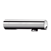
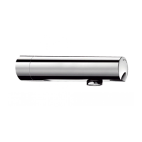
DRY WALLS
• To attach the box using the 4 legs, strengthen
the dry wall with 2 brackets.
• Seal the inside and lower edge of the box with
mastic to prevent any water leaking into the
wall. Position the silicone seal behind the
stainless steel wall plate to ensure a waterproof
seal between the wall plate and the wall. Leave
a drainage point to allow any residual water to
drain away.
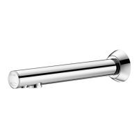
FIXING THE COVER
• Once the wall has been lined, attach the strips
onto the stainless steel case with 4 screws,
ensuring that they are level.
• Install the hydraulic unit.
• Feed the detector and solenoid valve cables
through the sheath.
• Connect the flexible to the spout and the
solenoid valve.
• Snap the cover onto the upper strip. After
testing, using a 2.5mm Allen key, tighten the 2
screws under the cover to tighten in place.
• Connect the solenoid valve and complete the
installation as shown in the CONNECTION
section.
THE INSTALLER MUST ENSURE THAT:
• THE RECESSING AREA IS WATERPROOF TO
PREVENT ANY INGRESS OF WATER;
• ANY WATER ACCIDENTALLY ENTERING THE
RECESSING AREA (E.G. (CONDENSATION, RUN
OFF, LEAKS, ETC.), IS NOT STAGNANT AND
HAS A DRAINAGE POINT;
• THE INTEGRITY OF THE SEALS BETWEEN THE
STAINLESS STEEL WALL PLATE AND THE WALL
OR THE WALL PLATE AND THE MIXER/TAP AT
LEAST ONCE A YEAR, AND MAKE GOOD IF
NECESSARY.
If this advice is not followed, water may
leak into the wall. DELABIE cannot be held
responsible for any ingress.
FOR FURTHER INFORMATION PLEASE CALL
TECHNICAL SUPPORT (SEE BELOW FOR
CONTACT DETAILS).
ELECTRICAL SUPPLY
• Electrical supply: 220-240V / 50 Hz class II
without earth connection. Install a 30 mA
c
irc
uit
bre
a
k
e
r
be
f
ore
t
he
e
le
c
t
ronic
c
ont
rol
box
(
not
supplie
d)
.
T
he
inst
a
lla
t
ion
m
ust
c
onf
or
m
t
o
l
o
c
al
El
ec
t
r
i
c
al
R
egu
l
at
i
on
s/St
and
ar
d
s an
d
m
u
st
b
e i
nst
al
l
ed
by
a c
o
m
pet
ent
, q
u
al
i
f
i
ed
el
ec
t
r
i
c
i
an
.
•
W
a
t
e
r
proof
e
le
c
t
ronic
box
IP
65.
•
If
t
he
supply
c
a
ble
is
da
m
a
ge
d
it
m
ust
be
re
pla
c
e
d
by
t
he
inst
a
lle
r.
•
T
he
e
le
c
t
ronic
box
1
(
f
ig.
A
,
B
,
C,
D,
E
)
is
supplie
d
by
220-
240V
~.
•
S
e
c
ure
t
he
c
a
ble
s
in
pla
c
e
wit
h
a
f
ix
e
d
rout
e
r
e
.
g.
a
r
igid
she
a
t
h
or
c
a
ble
holde
r.
C
ON
N
E
C
TION
-
H
YD
R
A
U
LIC
(
fig
. G
)
•
Res
pec
t
th
e
di
r
ec
ti
on
of
the
w
ater
fl
o
w
(
se
e
a
r
row
e
ngr
a
v
e
d
on
t
he
m
ix
e
r
/
t
a
p
body
)
.
I
n
s
tal
l
the
fi
l
ters
s
uppl
i
ed
t
o
prot
e
c
t
t
he
sole
noid
v
a
lv
e
(
s)
f
rom
f
ore
ign
bodie
s.
CONNECTION - E
LE
CTRICAL (fig. I)
•
Conne
c
t
the
sole
noi
d v
a
l
v
es t
o the t
er
minal EV
wit
h the
c
onne
c
t
or
prov
i
de
d.
• Connec
t
the
de
te
c
t
or
c
a
ble
t
o the
BMR
te
r
m
i
nal
v
i
a
the
c
om
pressi
on gla
nd:
-
WH
ITE wir
e: termin
al B
- B
RO
WN wir
e: termin
al M
- RED w
ir
e: terminal R
• D
o
not c
u
t or leng
then
the d
etector cable:
st
a
ndard lengt
h is 70c
m
(150 or
500cm lengt
hs
a
re
av
a
ilabl
e
on reque
st).
•
Conne
c
t to the
pow
e
r
supply
using an IEC
60227 PV
C insul
a
te
d tw
i
n-
c
ore power supply
c
a
ble
(2 x
1.5 or 2 x
1, ex
t
. Ø 7 - 8) t
o ensure a
w
a
te
rproof
c
onne
ct
i
on, c
onnect the
220-
240V
~ electrical supply to the 220-240 V~
term
inal connector
7
on the control unit via the
com
pression gland. A circuit breaker must be
installed ahead of the electronic control unit.
• Tighten the nuts on the com
pression glands.
• Mount the w
all box under the w
ashbasin at
least 50cm
above the floor w
ith the
compression glands facing downwards
.
• Replace the fixing screws, cover and seal then
close the box.