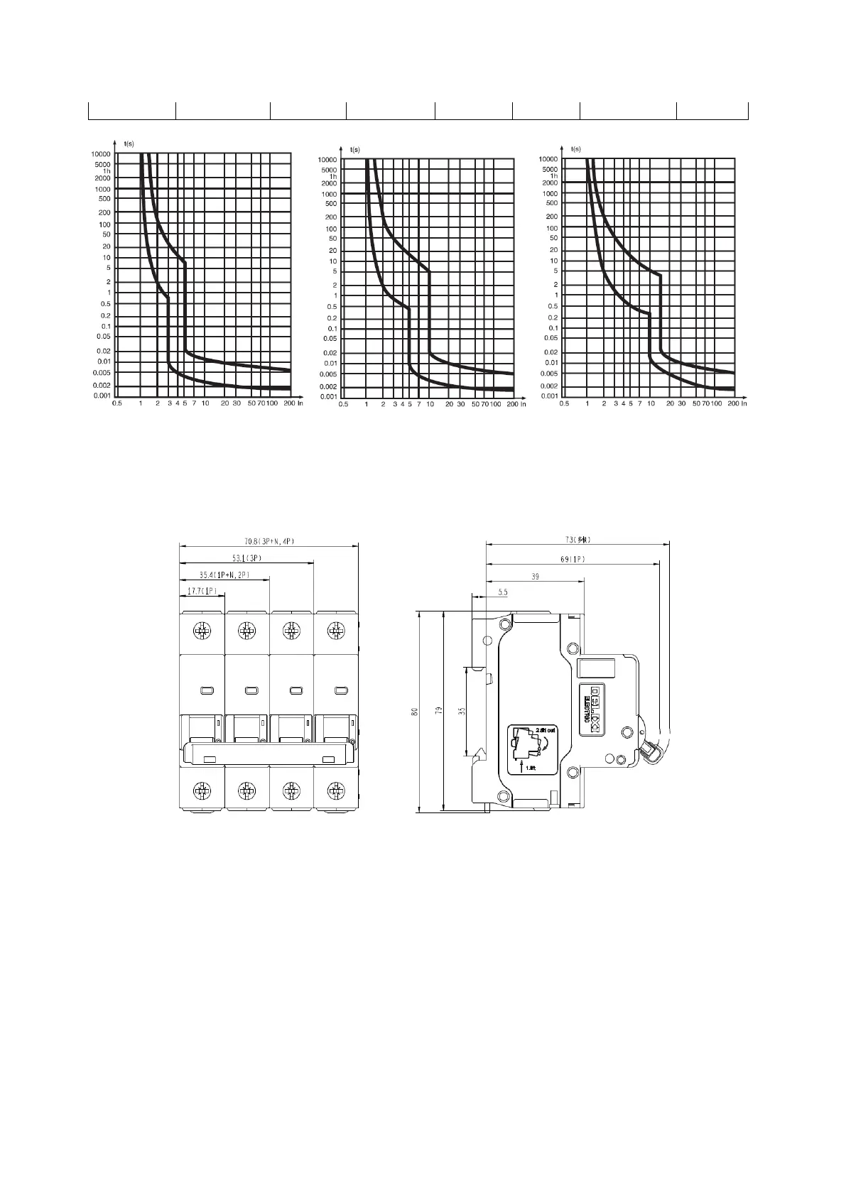
c) The protection characteristic curves of the circuit breaker are shown in Fig. 1 and Fig. 2, respectively.
Fig. 1 B type
thermal/electromagnetic trip
characteristic curve
Fig. 2 C type
thermal/electromagnetic trip
characteristic curve
Fig. 3 D type
thermal/electromagnetic trip
characteristic curve
5 Outline and installation dimensions
The outline and installation dimensions see Fig. 3.
Unit:mm
Fig. 3 Outline and installation dimensions
6 Installation and use (maintenance)
Before installing the circuit breaker:
a) Check whether the technical parameters on the printed sign meet the use requirements;
b) Before use, users should check that the insulation resistance between poles (expect for single pole), pole
and housing, pole and mounting rail, incoming terminal and outgoing terminal with a 500V megohmmeter
should not be less than 5MΩ. If the insulation resistance is less than 5MΩ, do not use the product and
contact the supplier for timely replacement;
c) Close and open the circuit breaker several times to check the circuit breaker operating mechanism for
blockage and for reliable action;
d) The reference temperature of this series of circuit breakers is
℃. If multiple circuit breakers are
installed in the sealed box, the temperature inside the box will increase accordingly, and the use current is
0.8In;
e) The cross-sectional area of the connecting wire should be compatible with the rated current of the circuit


 To Next Page