Procedure A, Task 2: Dell EMC Customer Engineer
Before you begin
Before connecting power to the system, make sure that the power for both zone A
and zone B are turned OFF. This task is performed by the Dell EMC Customer
Engineer.
Procedure
1. Confirm that the customer-supplied power cables are labeled and that each
label contains the relevant customer-supplied PDU and circuit breaker numbers.
If power cables are not equipped with labels, alert the customer.
2. Compare the numbers on the customer-supplied power cables for each storage
bay to verify that power zone A and power zone B are powered by a different
customer-supplied PDU.
3. Do one of the following to connect power zone A and power zone B in each bay.
l
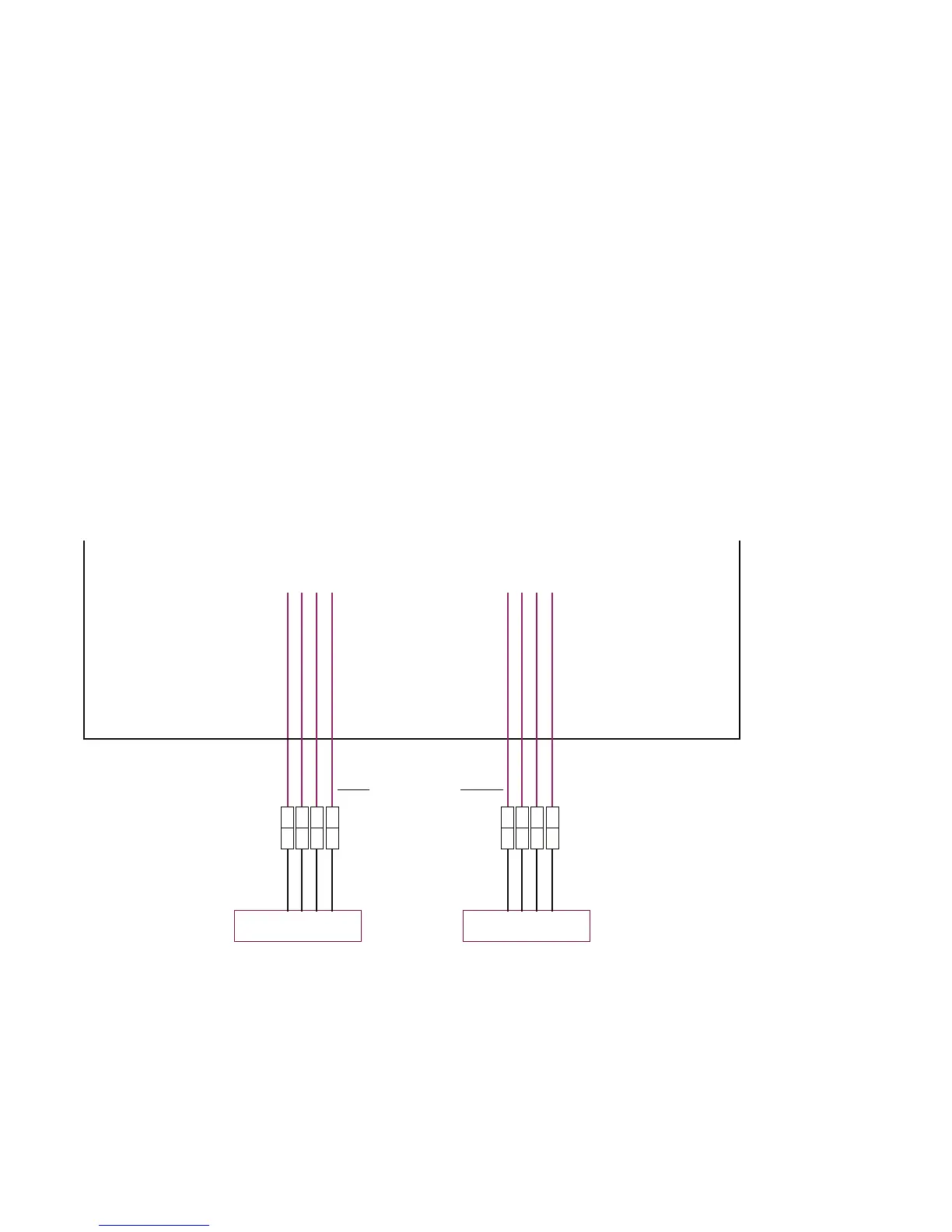
For single-phase power: Connect customer-supplied PDU power cables to
the storage bay by connecting to the bay's AC input cables for power zone A
and power zone B as shown below.
Figure 4 Connecting AC power, single-phase, PowerMax 2000
Customer’s PDU 1
Zone B
AC input
cable B
Mating connector or
customer-supplied cable
Customer’s PDU 2
Zone A
AC input
cable A
Mating connector or
customer-supplied cable
Dell EMC-supplied power cable
and connector from the PDU
Cable connectors are shown
as they exit the bottom rear
of the bay.
Rear view
System bay
Dell EMC-supplied power cable
and connector from the PDU
P1 P3 P4 P1 P3 P4
System #1: P1, P3
System #2: P4, P6
P3 and P6 used
depending on
conguration
P6 P6
Best Practices Guide for AC Power Connections
18 Best Practices Guide for AC Power Connections PowerMax 2000 and PowerMax 8000 with PowerMaxOS
 Loading...