Position PowerMax 8000 Bay
Positioning bays includes considering the layout and placement of the bays in the data center and placement on tiles. Each cabinet sits on
four caster wheels to aid in positioning the bay. Once the bay is positioned it can be secured with optional mounting bolts.
Topics:
• System bay layouts
• Dimensions for array layouts
• Tile placement
• Caster and leveler dimensions
• Cabinet stabilizing
System bay layouts
The number of bays and the system layout depends on the array configuration, the customer requirements, and the space and
organization of the customer data center.
Arrays can be placed in the following layouts:
• Adjacent — bays are positioned side-by-side.
• Dispersed — dispersed layouts are provided with longer MIBE optical and Ethernet cable bundles that allow 82 ft (25 m) of separation
between System Bay 1 and System Bay 2.
Dispersed system bays require dispersed cable and optics kits. When systems are ordered as dispersed, the dispersed bay is shipped
with two side skins installed.
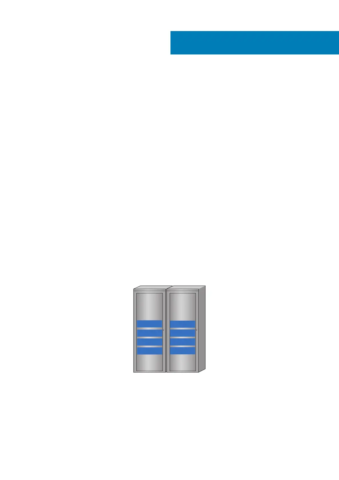
Adjacent layouts, PowerMax 8000
PowerMax 8000 systems with adjacent layouts position System Bay 1 next to System Bay 2.
The following figure shows the adjacent layout. The side skin on System Bay 1 that is adjacent to System Bay 2 is moved to the outer side
of System Bay 2.
System
bay 1
System
bay 2
Engine 4
Engine 3
Engine 7
Engine 8
Engine 2
Engine 1
Engine 6
Engine 5
Figure 7. Adjacent layouts, PowerMax 8000
Dispersed layout, PowerMax 8000
Systems with dispersed layouts use 98.4 ft (30m) optical cable bundles (single cable and spare) to connect SIBs to the MIBE and 98.4 ft
(30m) copper Ethernet cable bundles (single cable and spare) to connect MMs to the Ethernet switches. Cables are routed across the
subfloor or ceiling to connect the SIB and MM components in System Bay 2 to the MIBE and Ethernet switches in System Bay 1.
The following figure shows a dispersed layout for a PowerMax 8000 array.
7
30 Position PowerMax 8000 Bay
 Loading...