4-22 Dell PowerEdge 4100/180 and 4100/200 Systems Service Manual
4. Lift the microprocessor out of its socket.
To install the replacement microprocessor/heat sink assembly, ensure that the micro-
processor release lever is in its fully vertical position to allow the microprocessor pins
to easily slip into the socket. When the microprocessor/heat sink assembly is in place,
rotate the microprocessor release lever to its horizontal position. Hook the micro-
processor securing clip over the socket tab nearest the front of the system board, and
then snap it over the tab on the back of the socket.
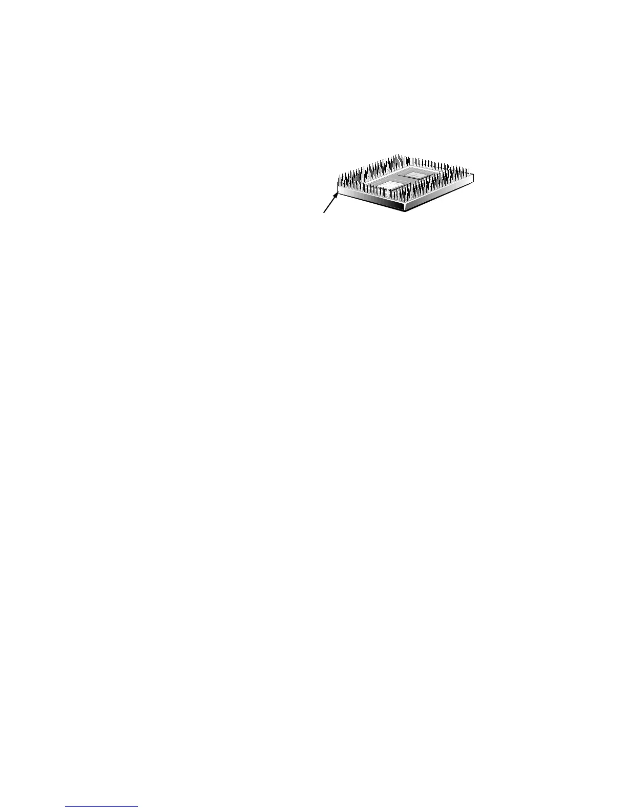
Figure 4-23. Pin-1 Identification
NOTE: Pin 1 on the microprocessor is located on the corner with the largest
bevel. The pin-1 hole in the microprocessor socket is located on the corner
where the holes are in a diagonal pattern.
If you are installing a new microprocessor and heat sink, place the thermal
interface pad that comes with the replacement microprocessor between the
microprocessor and the heat sink before reinstalling the securing clip.
pin-1 corner