Internal system components
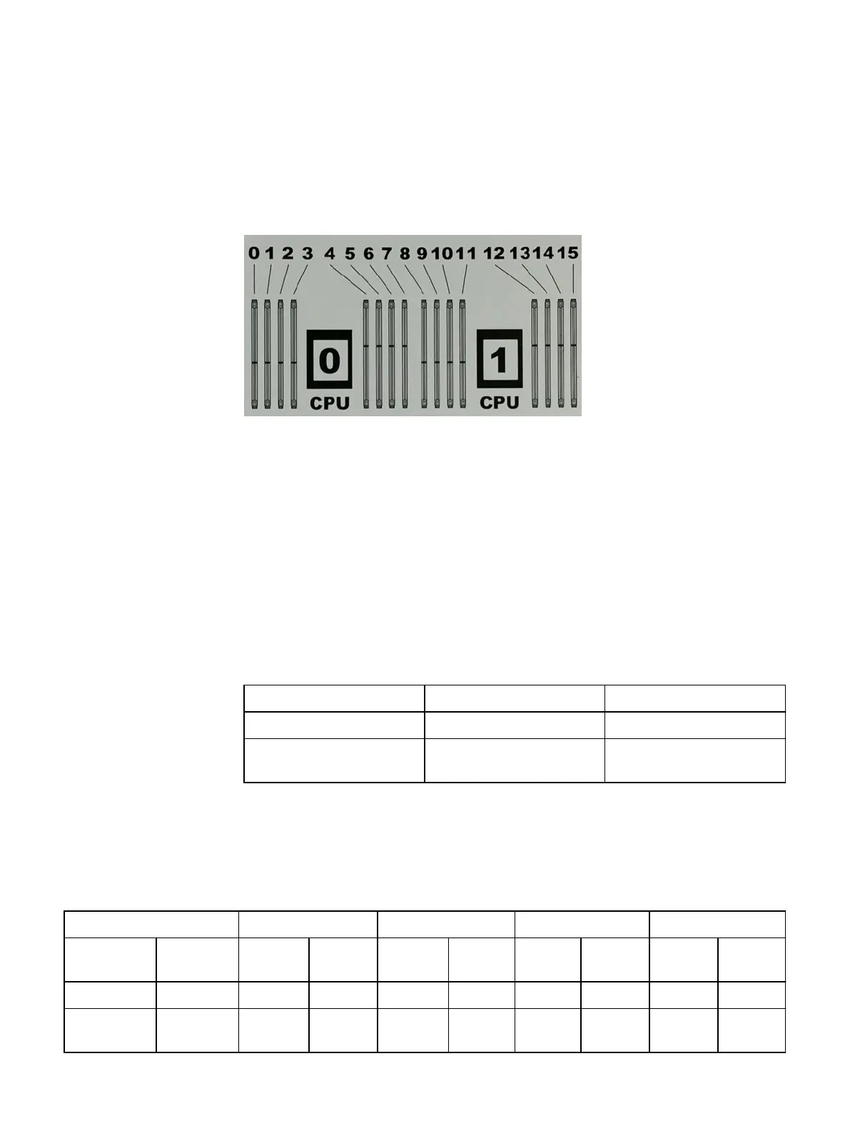
The following figure shows the layout of the CPUs and DIMMs inside the chassis. The
front of the system is at the top of the figure.
Figure 8 CPU and memory locations
DIMMs overview
Dual in-line memory modules (DIMM) come in various sizes, which must be configured
in a certain way. This topic can help you select the correct configuration when
servicing DIMMs.
The storage processor contains two Intel processors each with an integrated memory
controller that supports four channels of memory. The storage processor allows two
DIMM slots per channel, so the storage processor supports a total of 16 DIMM slots.
DD6800 memory DIMM configuration
Table 27
DD6800 memory DIMM configuration
Tier Total Memory Memory DIMM Configuration
DD6800 DLH 192 GB 8 x 16 GB +8 x 8 GB
DD6800 DLH Extended
Retention/DD Cloud Tier
192 GB 8 x 16 GB +8 x 8 GB
HA is supported with all available memory configurations.
To ensure maximum memory performance, there are memory DIMM population rules
for best memory loading and interleaving. Table 28 on page 33 and Table 29 on
page 34 specify the DIMM location rules for various memory configurations:
Table 28
Memory locations - CPU 0
Channel A Channel B Channel D Channel C
Tier Total
Memory
0 1 2 3 4 5 6 7
DD6800 DLH 192 GB 16 GB 8 GB 16 GB 8 GB 8 GB 16 GB 8 GB 16 GB
DD6800 DLH
Extended
192 GB 16 GB 8 GB 16 GB 8 GB 8 GB 16 GB 8 GB 16 GB
Data Domain DD6300, DD6800, and DD9300 Hardware Overview
Internal system components 33