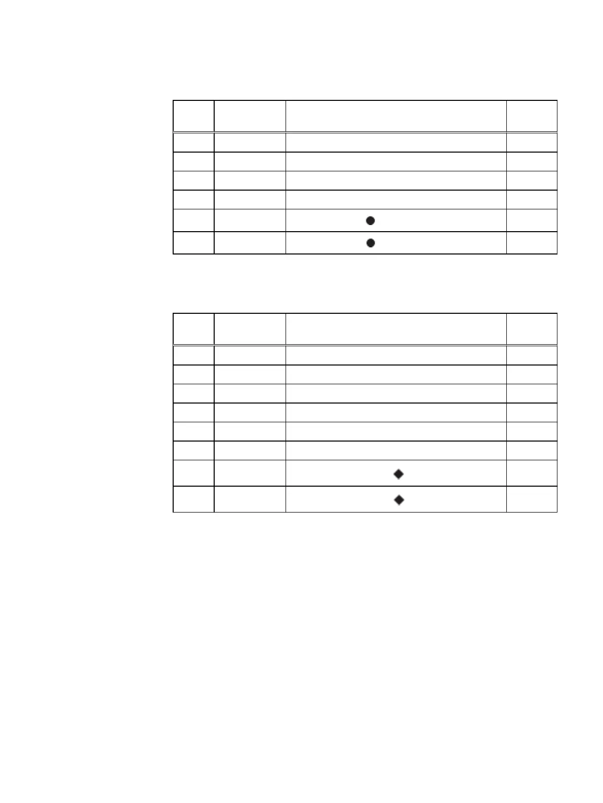
Table 46 Primary node cabling instructions (continued)
String
(Loop)
I/O - Port Shelf Port Length
a
2 I/O 7 - Port 1 A controller port 0 of shelf V2.1 2M
2 I/O 2 - Port 1 B controller port 0 of the highest number shelf in V2 2M
3 I/O 7 - Port 2 A controller port 0 of shelf V3.1 2M
3 I/O 2 - Port 2 B controller port 0 of the highest number shelf in V3 5M
4 I/O 7 - Port 3
A controller HOST port of the SSD shelf
2M
4 I/O 2 - Port 3
B controller HOST port of the SSD shelf
2M
a.
Cable lengths shown are designed for Data Domain racks. Longer cables (up to 5M) can be
used.
Table 47 Standby node cabling instructions
String
(Loop)
I/O - Port Shelf Port Length
a
1 I/O 7 - Port 0 B controller port 2 of shelf V1.1 2M
1 I/O 2 - Port 0 A controller port 2 of the highest number shelf in V1 2M
2 I/O 7 - Port 1 B controller port 2 of shelf V2.1 2M
2 I/O 2 - Port 1 A controller port 2 of the highest number shelf in V2 2M
3 I/O 7 - Port 2 B controller port 2 of shelf V3.1 2M
3 I/O 2 - Port 2 A controller port 2 of the highest number shelf in V3 5M
4 I/O 7 - Port 3
A controller EXPANSION port of the SSD shelf
2M
4 I/O 2 - Port 3
B controller EXPANSION port of the SSD shelf
2M
a.
Cable lengths shown are designed for Data Domain racks. Longer cables (up to 5M) can be
used.
Connect Cables and Power on
66 Data Domain DD6300, DD6800, and DD9300 Systems 6.1 Hardware Overview and Installation Guide