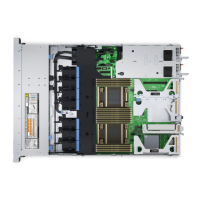
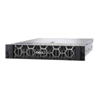
Table 12. Connector descriptions for 4 x 3.5-inch drive SAS or SATA backplane
From To
BP_PWR_1 (backplane power connector) SIG_PWR_1 (PIB board power connector)
BP_DST_SA1 (backplane SATA connector, cable marking BP
SA1)
CTRL_SRC_SA1 (Signal connector on the PERC)
Figure 24. Cable routing - 4 x 3.5-inch drive SAS or SATA backplane with butterfly riser, BOSS card
Table 13. Connector descriptions for 4 x 3.5-inch drive SAS or SATA backplane with Butterfly riser, BOSS
card
From To
J_PWR_1 (BOSS card connector) BOSS_PWR (Power connector for BOSS card on system
board)
LEFT EAR (LEFT EAR connector) LEFT_LED (LEFT_LED connector)
RIGHT EAR (RIGHT EAR connector) CTRL_PNL (Control panel connector)
INTRUDER R_INTRUSION
36 Installing and removing system components
 Loading...
