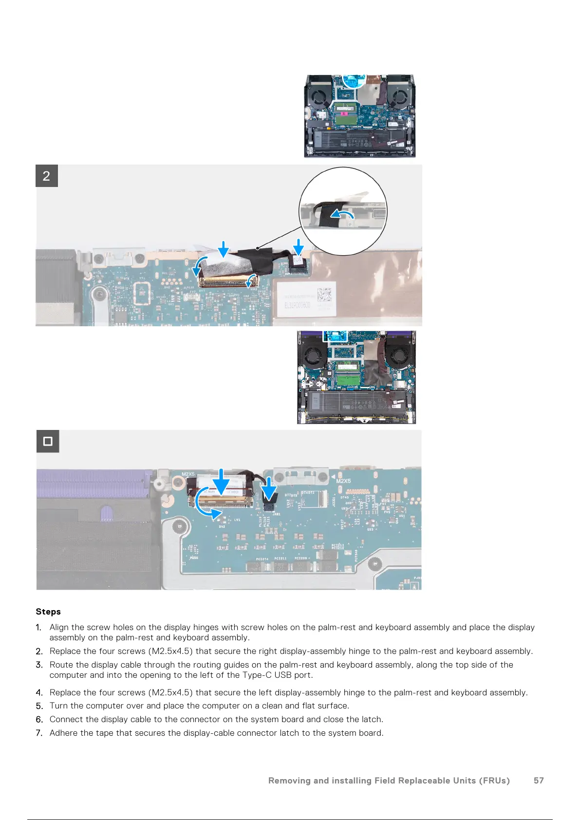
Steps
1. Align the screw holes on the display hinges with screw holes on the palm-rest and keyboard assembly and place the display
assembly on the palm-rest and keyboard assembly.
2. Replace the four screws (M2.5x4.5) that secure the right display-assembly hinge to the palm-rest and keyboard assembly.
3. Route the display cable through the routing guides on the palm-rest and keyboard assembly, along the top side of the
computer and into the opening to the left of the Type-C USB port.
4. Replace the four screws (M2.5x4.5) that secure the left display-assembly hinge to the palm-rest and keyboard assembly.
5. Turn the computer over and place the computer on a clean and flat surface.
6. Connect the display cable to the connector on the system board and close the latch.
7. Adhere the tape that secures the display-cable connector latch to the system board.
Removing and installing Field Replaceable Units (FRUs)
57
58 / 101 57 / 99 58 / 101