4 Route all the cables through the routing clips [1].
5 Align the cables with the pins on connectors on the system board and connect the following cables to the system board:
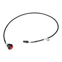
a Power switch [2]
b Power cable [3]
c CPU power [4]
d Intrusion switch [5]
6 Connect the power cable, optical drive data cable and hard drive data cable [1, 2, 3].
7 Insert the hook on the I/O panel into the slot on the chassis and rotate to close the I/O panel [4].
8 Replace the screw to secure the I/O panel to the chassis [5].
62
Disassembly and reassembly
 Loading...