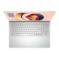
Steps
1. Align and place the power-button and fingerprint reader bracket on the palm-rest assembly.
2. Align the screw holes on the system board with the screw holes on the palm-rest assembly.
3. Replace the fours screws (M2x4), three screws (M1.2x3), and one screw (M1.2x4) that secure the system board to the
palm-rest assembly.
4. Connect the keyboard-controller board cable to the system board and close the latch to secure the cable.
5. Connect the speaker cable to the system board.
6. Adhere the fingerprint-reader board to the slot on the system board.
7. Connect the fingerprint-reader cable to the system board and close the latch to secure the cable.
8. Align the screw holes on the USB Type-C bracket to the screw holes on the system board.
9. Replace the screw (M1.6x3) and the screw (M1.6x2) that secures the USB Type-C port bracket to the system board.
NOTE: The M1.6x2 screw has a bigger head than the M1.6x3 screw.
10. Route the display cable and camera cable through the routing guides on the system board.
11. Connect the display cable and camera cable to the system board.
Removing and installing components
29
 Loading...