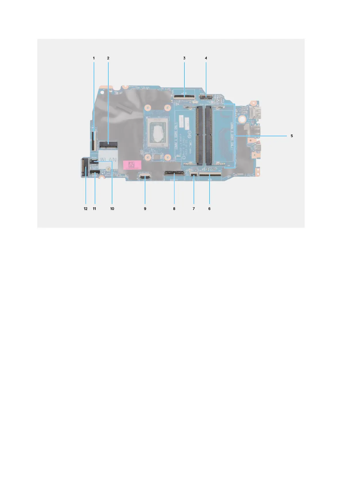
Figure 43. System board overview
1. I/O board cable (IO)
2. Wireless card slot (WLAN)
3. Display cable (eDP)
4. Power-adapter port cable (DCIN)
5. Memory slots x2 (DIMM A DDR5 ONLY + DIMM B DDR5 ONLY)
6. Keyboard cable (KB)
7. Keyboard-backlight cable (BL)
8. Battery cable (BATT)
9. Touchpad cable (TP)
10. Fan cable (FAN)
11. Speaker cable (SPK)
12. M.2 solid-state drive slot (SSD)
The following images indicate the location of the system board and provide a visual representation of the installation procedure.
84
Removing and installing Field Replaceable Units (FRUs)