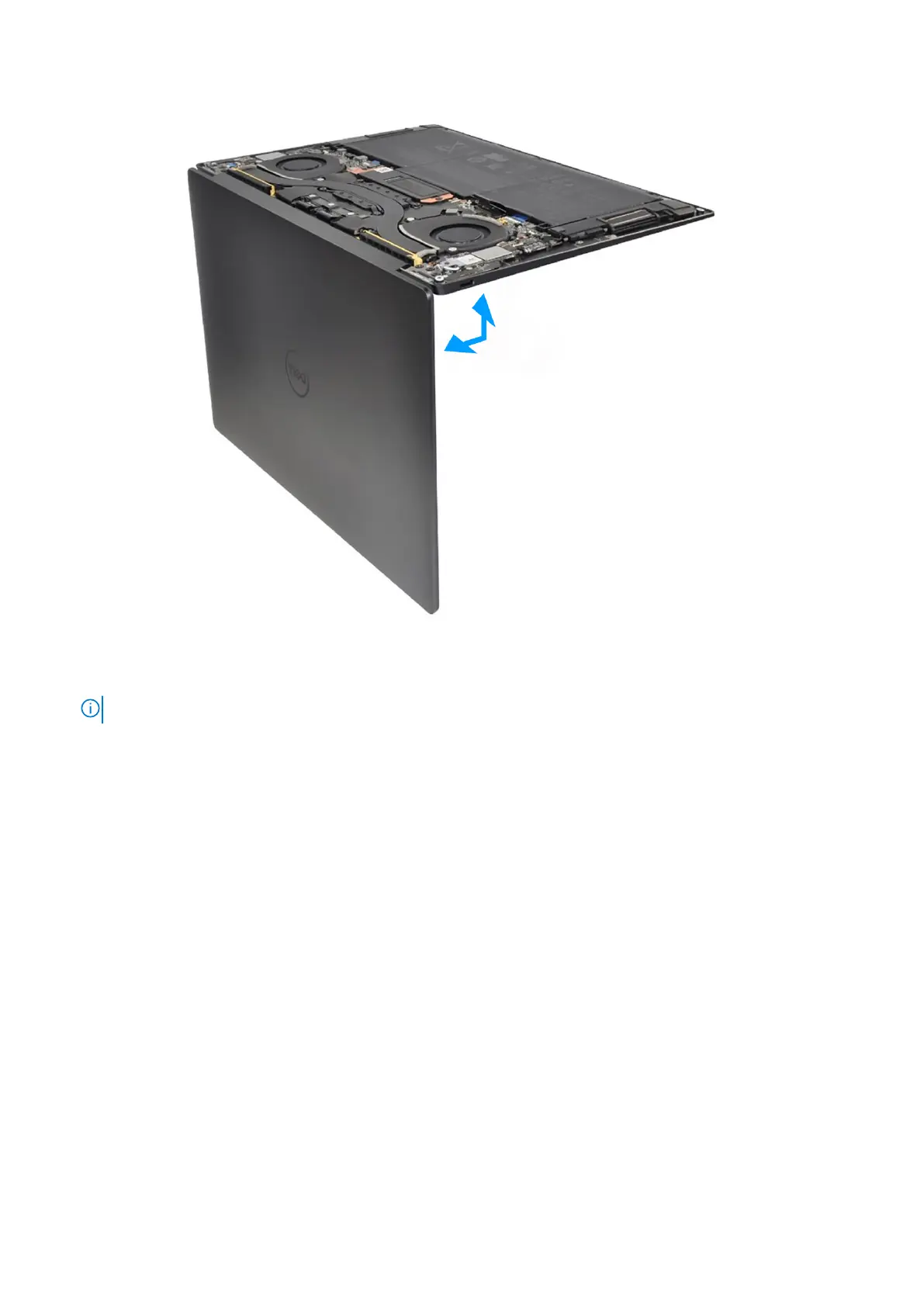
Figure 39. Opening the display assembly to a 90-degree angle
1. Loosen the captive screw (M1.6x2.3) that secures the wireless-module bracket to the system board.
NOTE: Be sure that the small, clear washer that holds the captive screw in place does not fall off.
2. Lift the wireless-module bracket off the system board.
3. Disconnect the wireless-module cables from the wireless module.
4. Loosen the three captive screws (M1.6x2) that secure the display-assembly cable bracket to the system board.
5. Lift the display-assembly cable bracket off the system board.
6. Disconnect the camera cable and the display cable from the system board.
7. Lift the latch of the capacitive touch-panel connector and use the pull tab of the cable to disconnect the capacitive
touch-panel cable.
8. Use the pull tab to disconnect the left-speaker cable.
9. Lift the latch of the haptic-module cable connector and use the pull tab of the cable to disconnect the haptic-module cable.
10. Lift the latch of the keyboard control-board connector and use the pull tab of the cable to disconnect the keyboard
control-board cable.
11. Use the pull tab to disconnect the right-speaker cable.
12. Lift the latch of the power-button connector and use the pull tab of the cable to disconnect the power-button cable.
13. Remove the four screws (M1.6x3) that secure the system board to the palm-rest and keyboard assembly.
14. Remove the seven screws (M1.6x2.3) that secure the system board to the palm-rest and keyboard assembly.
15. Hold the system board by the short edges, as shown in the image, and lift the board off the palm-rest and keyboard
assembly with care.
58
Removing and installing Field Replaceable Units (FRUs)