EasyManua.ls Logo

Dell P780 - 17" CRT Display User Manual

Dell P780 - 17" CRT Display
61 pages
To Next Page IconTo Next Page
Page #1 background imageLoading...
Page #1 background image
SPECIFICATIONS
D99
CHASSIS
SERVICE MANUAL
P780
P780
Equator Model
Japan Model
N. Hemisphere Model
S. Hemisphere Model
Chassis No. L29K-A
COLOR MONITOR
Picture tube
Video image area
Resolution
Standard image area
Input signal
Video
Sync
0.24-0.25 mm aperture grill pitch
17 inches measured diagonally
90-degree deflection
(16" maximum viewing image)
Approx. 326 X 243 mm (w/h)
(12
7/8
x 9
5/8
inches)
Horizontal: Max. 1280 dots
Vertical: Max. 1024 lines
Approx. 312 x 234 mm (w/h)
(12
1/4
x 9
1/4
inches)
Analog RGB (75 ohms typical)
0.7 Vp-p,
±
5%, Positive
Separate HD/VD,
TTL Polarity Free
External Composite,
TTL Polarity Free (2K ohms impedance)
Power Consumption
Deflection frequency
AC input voltage / current
Dimensions
Mass
Maximum 120W
Minimum 95W
Horizontal: 30 to 85 KHz
Vertical: 48 to 120 Hz
100 to 120 V, 50/60 Hz, 1.7A
220 to 240V, 50/60Hz, 0.9A
414 x 404 x 420mm (w/h/d)
(16
1/4
x 15
7/8
x 16
1/2
inches)
Approx. 18.8 kg (41 lbs. 8 oz.)
Design and specifications are subject to change without notice.
Question and Answer IconNeed help?

Do you have a question about the Dell P780 - 17" CRT Display and is the answer not in the manual?

Dell P780 - 17" CRT Display Specifications

General IconGeneral
Display TypeCRT
Maximum Resolution1280 x 1024
Dot Pitch0.25 mm
Horizontal Refresh Rate30 - 96 kHz
Vertical Refresh Rate50 - 160 Hz
ManufacturerDell
ModelP780
Screen Size17 inches
Viewable Image Size16 inches
Input SignalAnalog
Refresh Rate60 - 85 Hz

Summary

Specifications

Power Management

Power Saving Modes Explained

Describes different power saving states and their characteristics.

Self Diagnosis Function

LED Error Indicators

Explains LED indicators for self-diagnosis errors.

Timing Specification

Safety Check-Out

AC Leakage Test Procedure

Instructions for measuring AC leakage current from metal parts.

Monitor Customization Guide (OSD Functions)

Picture Quality (Convergence) Adjustment

Eliminating color shadows for clearer picture quality.

Picture Size and Centering Adjustment

How to adjust horizontal and vertical picture size and position.

Picture Shape (Geometry) Adjustment

Adjusting geometry settings like rotation and keystone.

Picture Color Temperature Adjustment

How to adjust color temperature and fine-tune colors.

Warning Messages

Out of Scan Range Message

Message indicating inappropriate input signal range.

Troubleshooting Common Issues

No Picture or LED Off

Steps to take when the monitor shows no picture or is dead.

No Picture or Low Brightness

Troubleshooting for no picture or lack of brightness.

Poor Picture Focus

Solutions for blurry or fuzzy picture issues.

Picture Centering and Sizing Issues

Steps to correct improper picture centering or sizing.

Curved Image Edges

Troubleshooting curved image edges.

Moire Pattern Correction

How to address moire patterns on the screen.

Non-Uniform Color Display

Solutions for non-uniform color display.

White Color Representation Issues

Troubleshooting issues with white color representation.

Troubleshooting Common Issues (Continuation)

Shaky or Jittery Video

Solutions for video instability or jitter.

Color Purity Problems

Addresses issues with color purity or blotches.

Color Convergence Problems

Solutions for color convergence issues.

Missing Color or Color Cast

Troubleshooting missing colors or color cast.

Dead or Stuck Pixels

Addresses issues with dead or stuck pixels.

Picture Brightness Issues

Solutions for pictures being too dim or too bright.

PICTURE TUBE REMOVAL

Anode Cap Removal Warning

Critical safety warning before anode cap removal.

Anode Cap Removal Procedure

Detailed steps for safely removing the anode cap.

SECTION 3 SAFETY RELATED ADJUSTMENTS

High Voltage (HV) Adjustment

Adjusting High Voltage (HV) levels.

HV Regulator Circuit Check

Checking the High Voltage regulator circuit.

HV Hold Down Circuit Check

Verifying the HV hold-down circuit functionality.

Beam Current Protector Check

Checking beam current protection logic.

B+ Voltage Check

Verifying the B+ voltage level.
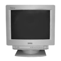
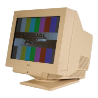
Related product manuals