2. From inside the system, push the control panel out of the chassis.
3. Remove all the cables connecting the control panel to the chassis.
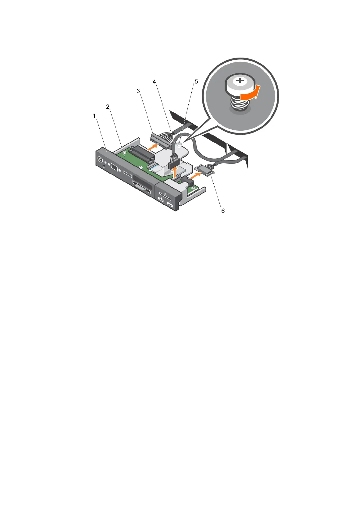
Figure 115. Removing the control panel—3.5 inch hard drive system
1.
control panel 2. control panel board
3. control panel connector cable 4. USB connector cable
5. screw 6. vFlash media connector cable
174 Installing and removing system components