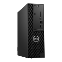
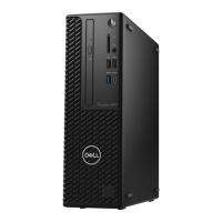
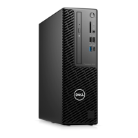
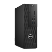
Do you have a question about the Dell Precision 3431 and is the answer not in the manual?
Essential safety guidelines for handling computer hardware and ensuring personal safety during maintenance.
Procedure to properly shut down the computer, ensuring data integrity before internal access.
Preparatory steps and precautions to take before opening the computer for maintenance or repair.
Steps to follow after completing internal work, ensuring all components are reconnected and secured.
Details on the processor types and specifications available for the system.
Explanation of DDR4 memory technology, its features, and differences from older types.
Overview of Universal Serial Bus (USB) standards and their evolution, including transfer rates.
Information on the USB Type-C connector, its capabilities, and compatibility with USB 3.1.
Details about the HDMI 2.0 interface, its features, and advantages for audio/video transmission.
Comparison highlighting the benefits of DisplayPort when used via a USB Type-C connection.
Identifies the computer's side panel as a major system component.
Identifies the CPU cooling assembly (heatsink and fan) as a major system component.
Identifies the hard drive, the primary storage device, as a major system component.
Identifies the bracket securing the hard drive as a major system component.
Identifies the combined module for hard drive and optical drive as a system component.
Identifies the optical drive (CD/DVD) as a major system component.
Identifies the power switch as a major system component.
Identifies the system board (motherboard) as the central component of the system.
Identifies the Input/Output panel on the front or rear as a major system component.
Identifies the system cooling fan as a major component.
Identifies the internal speaker as a component of the system.
Identifies the memory modules (RAM) as major system components.
Identifies the processor (CPU) as a key component of the system.
Identifies the power supply unit (PSU) as a critical system component.
Identifies the graphics card as a potentially major system component.
List of specialized tools required for performing component removal and installation procedures.
A table detailing screw types and their corresponding components for accurate assembly.
Diagram identifying key connectors and components on the system's motherboard.
Instructions for removing and installing the computer's side panel for internal access.
Step-by-step guide for removing and installing expansion cards, such as graphics or network cards.
Procedures for replacing the coin cell battery, typically used for BIOS settings and system clock.
Detailed instructions for removing and installing hard drive assemblies, including 2.5-inch and 3.5-inch drives.
Steps to remove and install the front panel bezel, providing access to front-mounted components.
Procedures for handling the combined module containing the hard drive and optical drive.
Steps for removing and installing the optical drive (e.g., CD/DVD drive) within the system.
Instructions for removing and installing RAM modules (DIMMs) to upgrade or replace memory.
Procedures for removing and installing the CPU heat sink and cooling fan assembly.
Steps for removing and installing the chassis intrusion detection switch.
Instructions for removing and installing the system's power button assembly.
Detailed steps for removing and installing the central processing unit (CPU).
Procedures for removing and installing M.2 PCIe solid-state drives, including thermal pad considerations.
Steps for removing and installing Intel Optane memory cards, including thermal pad requirements.
Instructions for removing and installing the optional SD card reader module.
Procedures for removing and installing internal antennas, typically for wireless connectivity.
Steps for removing and installing external antennas, often used for wireless network cards.
Instructions for removing and installing M.2 2230 form factor wireless LAN cards.
Procedures for removing and installing the computer's power supply unit (PSU).
Steps for removing and installing the internal system speaker.
Instructions for removing and installing the system cooling fan.
Detailed procedures for removing and installing the main system board (motherboard).
Overview of the ePSA diagnostics tool for hardware health checks before the OS loads.
Step-by-step instructions on how to initiate and run the ePSA diagnostic tests.
Explanation of the POST (Power-On Self Test) and LED status indicators for system diagnostics.
Descriptions of common error messages encountered during diagnostics and troubleshooting.
Explanations of system error messages that may appear during boot-up or operation.
Information on how to contact Dell support for assistance, including online and phone options.
| Display included | No |
|---|---|
| Mouse included on selected markets only | Yes |
| Tcase | 69.3 °C |
| Tjunction | 100 °C |
| Processor cache | 8 MB |
| Processor cores | 4 |
| System bus rate | - GT/s |
| Processor socket | LGA 1151 (Socket H4) |
| Processor codename | Coffee Lake |
| Processor frequency | 3.4 GHz |
| Processor lithography | 14 nm |
| Processor manufacturer | Intel |
| PCI Express slots version | 3.0 |
| Processor boost frequency | 4.6 GHz |
| Processor operating modes | 64-bit |
| PCI Express configurations | 1x16, 2x8, 1x8+2x4 |
| Thermal Design Power (TDP) | 71 W |
| Number of processors installed | 1 |
| Maximum number of PCI Express lanes | 16 |
| Memory types supported by processor | DDR4-SDRAM |
| Memory clock speeds supported by processor | 2666 MHz |
| Maximum internal memory supported by processor | 128 GB |
| CUDA cores | 640 |
| On-board graphics card | - |
| Discrete graphics card model | NVIDIA® Quadro® P1000 |
| On-board graphics card model | Not available |
| Discrete graphics card memory | 4 GB |
| Discrete graphics memory type | GDDR5 |
| SSD capacity | The Solid State Drive's storage capacity in Gigabytes. |
| SSD interface | NVMe, PCI Express |
| Storage media | SSD |
| SSD form factor | M.2 |
| Optical drive type | DVD±RW |
| Total storage capacity | 256 GB |
| Operating system installed | Windows 10 Pro for Workstations |
| Memory slots | 4x DIMM |
| Internal memory | 16 GB |
| Maximum internal memory | 64 GB |
| Memory layout (slots x size) | 2 x 8 GB |
| Power supply | 260 W |
| 80 PLUS certification | 80 PLUS Platinum |
| Power supply input voltage | 100 - 240 V |
| Power supply input frequency | 50 - 60 Hz |
| Cabling technology | 10/100/1000Base-T(X) |
| Ethernet LAN data rates | 10, 100, 1000 Mbit/s |
| Audio chip | Realtek ALC3234 |
| Audio system | High Definition Audio |
| Product type | Workstation |
| USB 2.0 ports quantity | USB 2.0 ports have a data transmission speed of 480 Mbps, and are backwards compatible with USB 1.1 ports. You can connect all kinds of peripheral devices to them. |
| Number of USB ports with PowerShare support | 2 |
| USB 3.2 Gen 1 (3.1 Gen 1) Type-A ports quantity | 5 |
| USB 3.2 Gen 1 (3.1 Gen 1) Type-C ports quantity | 0 |
| Volume | 7.8 L |
| Chassis type | SFF |
| Product color | Black |
| Placement supported | Horizontal/Vertical |
| Scalability | 1S |
| Processor ARK ID | 191036 |
| Processor package size | 37.5 x 37.5 mm |
| Supported instruction sets | SSE4.1, SSE4.2, AVX 2.0 |
| Depth | 292 mm |
|---|---|
| Width | 92.6 mm |
| Height | 290 mm |
| Weight | 5117 g |

