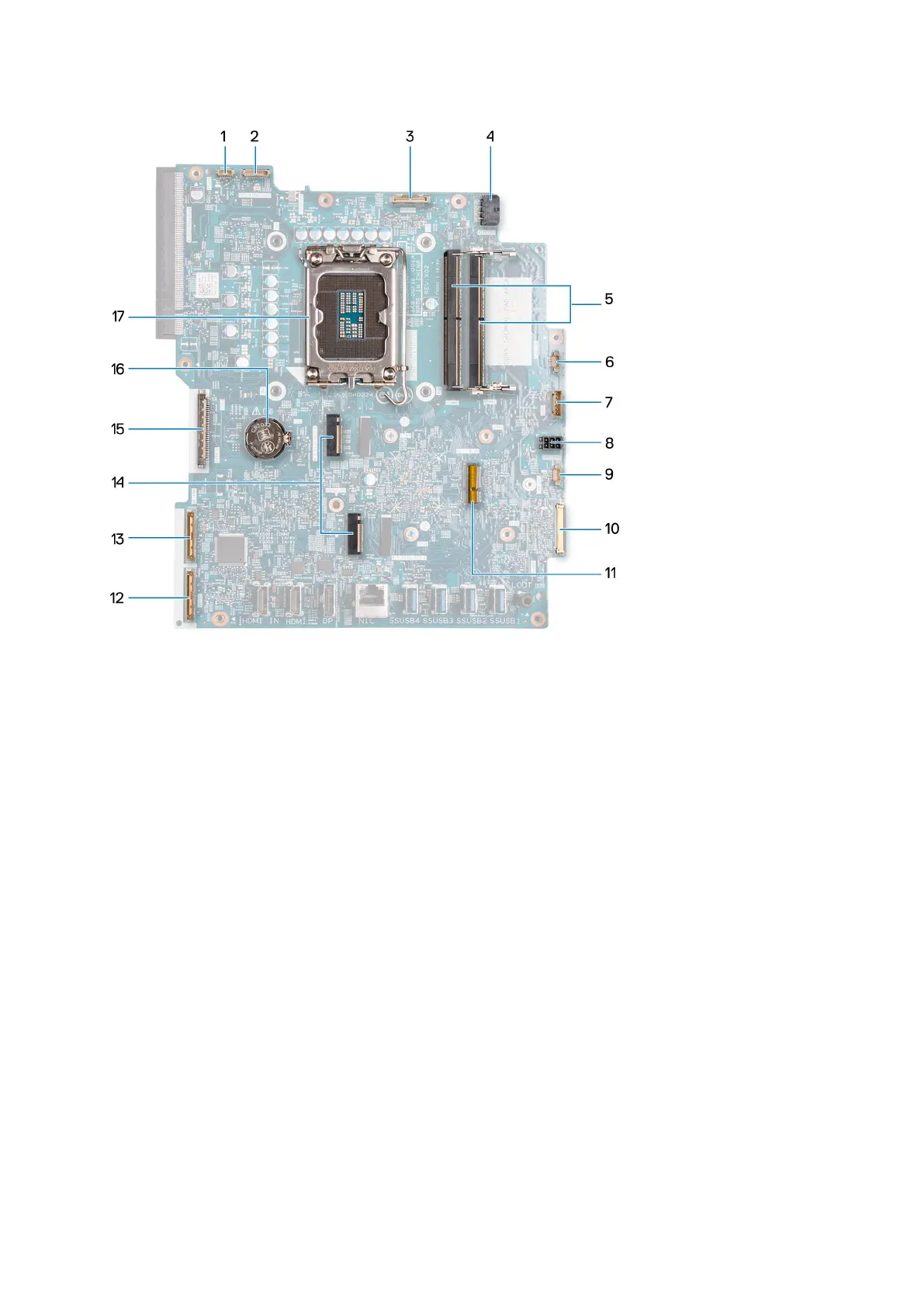
1. Touchscreen cable (TOUCH)
2. Display-backlight cable (LCD BACKLIGHT)
3. Camera cable (WEBCAM)
4. Processor-power cable (ATX CPU)
5. Memory slots (DIMM1 + DIMM2)
6. Fan cable (FAN CPU)
7. Control-signal cable (CTRL)
8. System-board power cable (ATX SYS)
9. Power-supply fan cable (FAN SYS)
10. audio cable (MB-AUDIO)
11. Wireless-card slot (M.2 WLAN)
12. high-speed cable (MB-HS)
13. power cable (MB-PWR)
14. Solid-state drive slots (M.2 PCIe SSD 1 + M.2 PCIe SSD 0)
15. Display cable (CVDS)
16. Coin-cell battery socket (RTC)
17. Processor socket (CPU)
The following image(s) indicate the location of the system board and provides a visual representation of the removal procedure.
Removal and installation procedures for High Performance processors
91