Figure 1
Figure 2
6
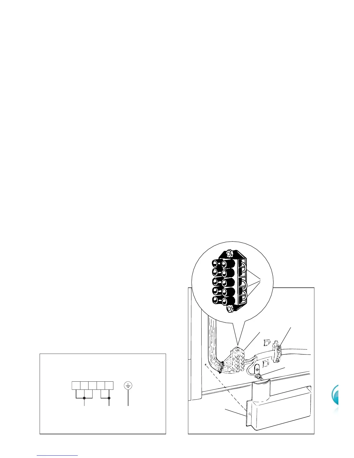
CONNECTING THE FEEDER CABLE
Important!
This cooker must be connected to the electricity supply only by an autho-
rised person.
To connect the feeder cable to the cooker it is necessary to:
■ Remove the screws that hold shield A behind the cooker (fig. 2).
■ Fitted with a 5-pole terminal block, position the U bolts “C” onto terminal block “B”
according to the diagram in fig. 1.
■ Feed the supply cable through the cable clamp “D”. The supply cable must be of a
suitable size for the current requirements of the appliance; see the section “Feeder
cable section”.
■ Connect the phase wires to the terminal block “B” and the earth wire to the terminal
“PE” as shown in figure 2.
■ Take up any slack in the cable and secure with the cable clamp “D”.
■ Replace the cover “A”.
N.B. The earth conductor must be left about 3 cm longer than the others.
Voltage and power consumption
230 V~ 50 Hz 8700 W (37.8 A) (diversity not applied)
240 V~ 50 Hz 9500 W (39.5 A) (diversity not applied)
Feeder cable section
This cooker must be connected to
electrical supply using V105 insu-
lated cable.
230-240 V~ 3 x 4 mm
2
(*)
(*)
Connection with wall box connection.
- Diversity factor applied
- A diversity factor may be applied to
the total loading of the cooker only
by a suitably qualified person.
B
A