P/N XG0511
Page 3
Hotshot Gas Fireplace Insert
Installation
Installing The Gas Line
The gas line must be installed before finishing the Hotshot
fireplace insert. For ease of installation, this appliance is equipped
with an approved flexible gas connector. The connector is factory-
installed and can be connected to the gas line as shown in figure
2.
Natural Gas requires a minimum inlet gas supply pressure of 5.5"
W.C. & a manifold pressure of 3.5" W.C. Propane Gas requires a
minimum inlet gas supply pressure of 11" W.C. & a manifold
pressure of 10" W.C. The fireplace gas connection and the main
operating gas valve is located behind the removable brass trim at
the bottom of the unit and need only be attached to the gas line
with an approved fitting, as required by the applicable
installation codes.
The appliance and its individual shutoff valve must be
disconnected from the gas supply piping system during any
pressure testing of that system at test pressures in excess of 1/2
psig (3.5 kPa).
The appliance must be isolated from the gas supply piping system
by closing its individual manual shutoff valve during any pressure
testing of the gas supply piping system at test pressures equal to
or less than 1/2 psig (3.5 kPa).
Before You Begin
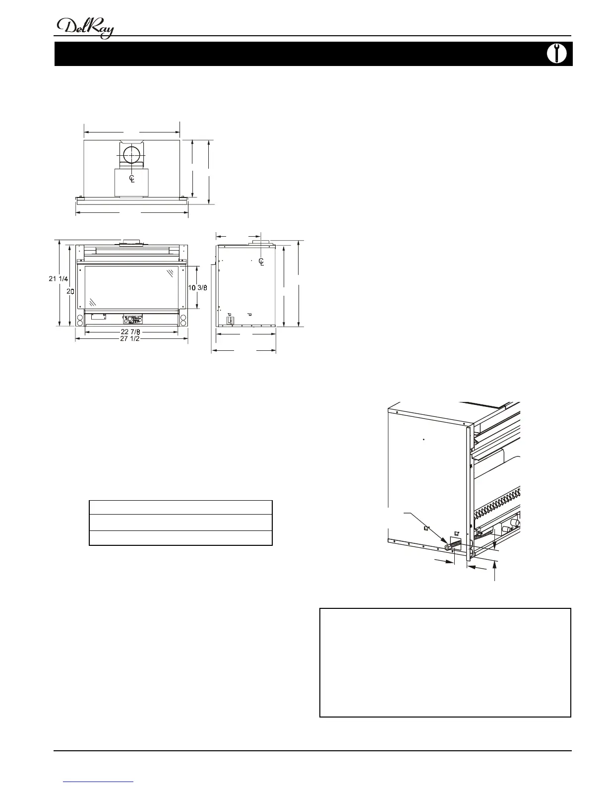
Ensure that your masonry fireplace's opening is large enough to
accomodate the Hotshot. The insert's dimensions are shown below:
Front View
Side View
27 1/2
24
15 3/4
14
10 1/2
20
15 3/4
14
21 1/4
Figure 1. Fireplace dimensions.
n Thoroughly clean the masonry or solid fuel fireplace and chimney
that in which the insert will be installed.
n The appliance has a gas access hole on the left hand side, and it
is supplied with a flexible gas connector on the left hand side of
the insert (See figure 2). A 1/2" gas supply pipe must be brought
near this connection before installing the hotshot insert.
Top View
Clearances
The DHS' clearances to combustible materials are:
Perpendicular Wall 3"
Floor Non-combustible
Mantle (10" wide)* 18 ½"
* Refer to page 4.
Unprotected combustible walls which are perpendicular to the fireplace
opening, must not be closer than 3" to the faceplate.
The DHS must be installed in a masonry or factory-built solid fuel
fireplace with a hearth extending 16" from the fireplace facing. This
appliance is not for installation in air tight units.
Figure 2. Gas line location.
Note: After the gas line is connected, each appliance
connection, valve and valve train must be checked
while under normal operating pressure with either a
liquid solution, or leak detection device, to locate any
source of leak. Tighten any areas where bubbling
appears or leak is detected until bubbling stops
completely or leak is no longer detected. DO NOT use
a flame of any kind to test for leaks.