Chapter 3 Connections and Wiring
Revision January 2011 3-61
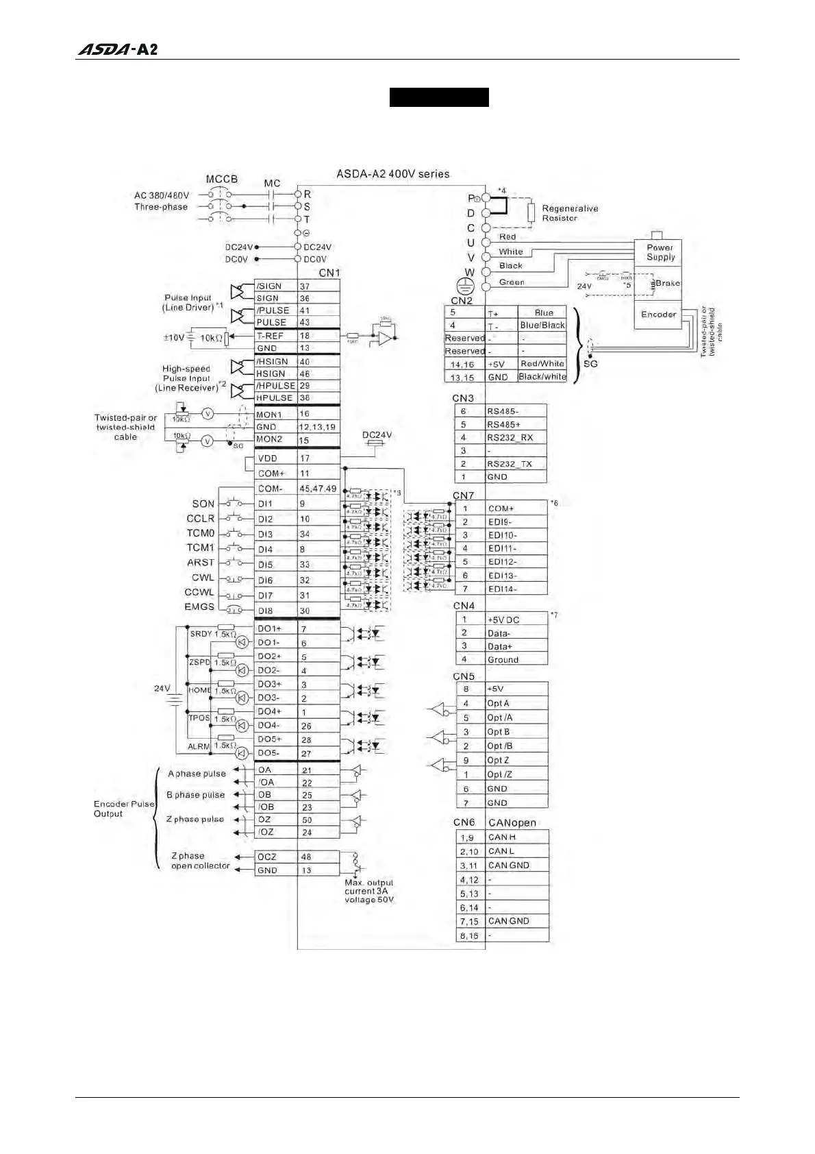
3.12 Standard Connection Example – 400V series
3.12.1 Position (PT) Control Mode
Please note:
*1 Please refer to C3 ~ C4 wiring diagrams in section 3.4.4.
*2 Please refer to C3 ~ C4 wiring diagrams in section 3.4.4.
*3 Please refer to C9 ~ C12 wiring diagrams (SINK / SOURCE mode) in section 3.4.4.
*4 400W and below drives do not provide built-in regenerative resistor.
*5 The coil of brake has no polarity.
*6 For extension digital inputs (DI) connections (CN7 is a optional part, not Delta standard supplied part.).
*7 For USB connection. It is used to connect to personal computer or notebook.
Call 1(800)985-6929 for Sales
Call 1(800)985-6929 for Sales