Chapter 5 Trial Run and Tuning Procedure
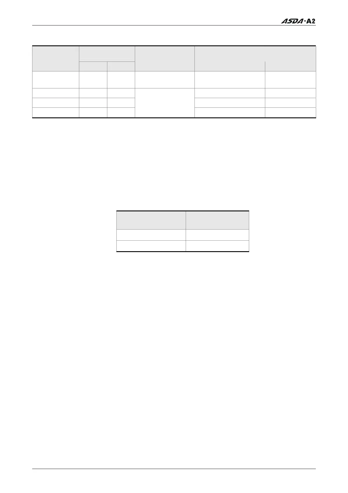
The speed command is selected by SPD0, SPD1. Please refer to the following table:
DI signal of CN1
Speed
Command No.
SPD1 SPD0
Command Source
Content Range
S1 0 0
External analog
command
Voltage between V-REF
and GND
-10V ~ +10V
S2 0 1 P1-09 -60000 ~ 60000
S3 1 0 P1-10 -60000 ~ 60000
S4 1 1
Internal parameter
P1-11 -60000 ~ 60000
0: indicates OFF (Normally Open); 1: indicates ON (Normally Closed)
The range of internal parameter is from -60000 to 60000.
Setting value of speed command = Setting range x unit (0.1 r/min).
For example:
If P1-09 is set to +30000, the setting value of speed command = +30000 x 0.1 r/min = +3000
r/min.
The settings of speed command:
P1-09 is set to +30000
Input value
command
Rotation direction
P1-10 is set to +1000 + N(CW)
P1-11 is set to -30000 - P(CCW)
STEP 3:
1. The users can use DI1 to enable the servo drive (Servo On).
2. If DI3 (SPD0) and DI4 (SPD1) are OFF both, it indicates S1 command is selected. At this
time, the motor is operating according to external analog command.
3. If only DI3 is ON (SPD0), it indicates S2 command (P1-09 is set to +30000) is selected,
and the motor speed is 3000r/min at this time.
4. If only DI4 is ON (SPD1), it indicates S3 command (P1-10 is set to +1000) is selected,
and the motor speed is 100r/min at this time.
5. If DI3 (SPD0) and DI4 (SPD1) are ON both, it indicates S4 command (P1-11 is set to -
30000) is selected, and the motor speed is -3000r/min at this time.
6. Repeat the action of (3), (4), (5) freely.
7. Wh
en
the users want to stop the speed trial run, use DI1 to disable the servo drive
(Servo Off).
5-10 Revision January 2011
Call 1(800)985-6929 for Sales
Call 1(800)985-6929 for Sales