Chapter 6 Control Modes of Operation
6.6.3 Analog Monitor
Users can use analog monitor to observe the required analog voltage signals. ASDA-A2
series servo drives provide two analog channels, they are PIN No. 15 and 16 of CN1
connector. The parameters relative to analog monitor are shown below.
Relevant parameters:
P0 - 03 MON Analog Monitor Output Address: 0006H, 0007H
Default: 01 Related Section:
Applicable Control Mode: ALL Section 4.3.5
Unit: N/A
Range: 00 ~ 77
Data Size: 16-bit
Display Format: Hexadecimal
Settings:
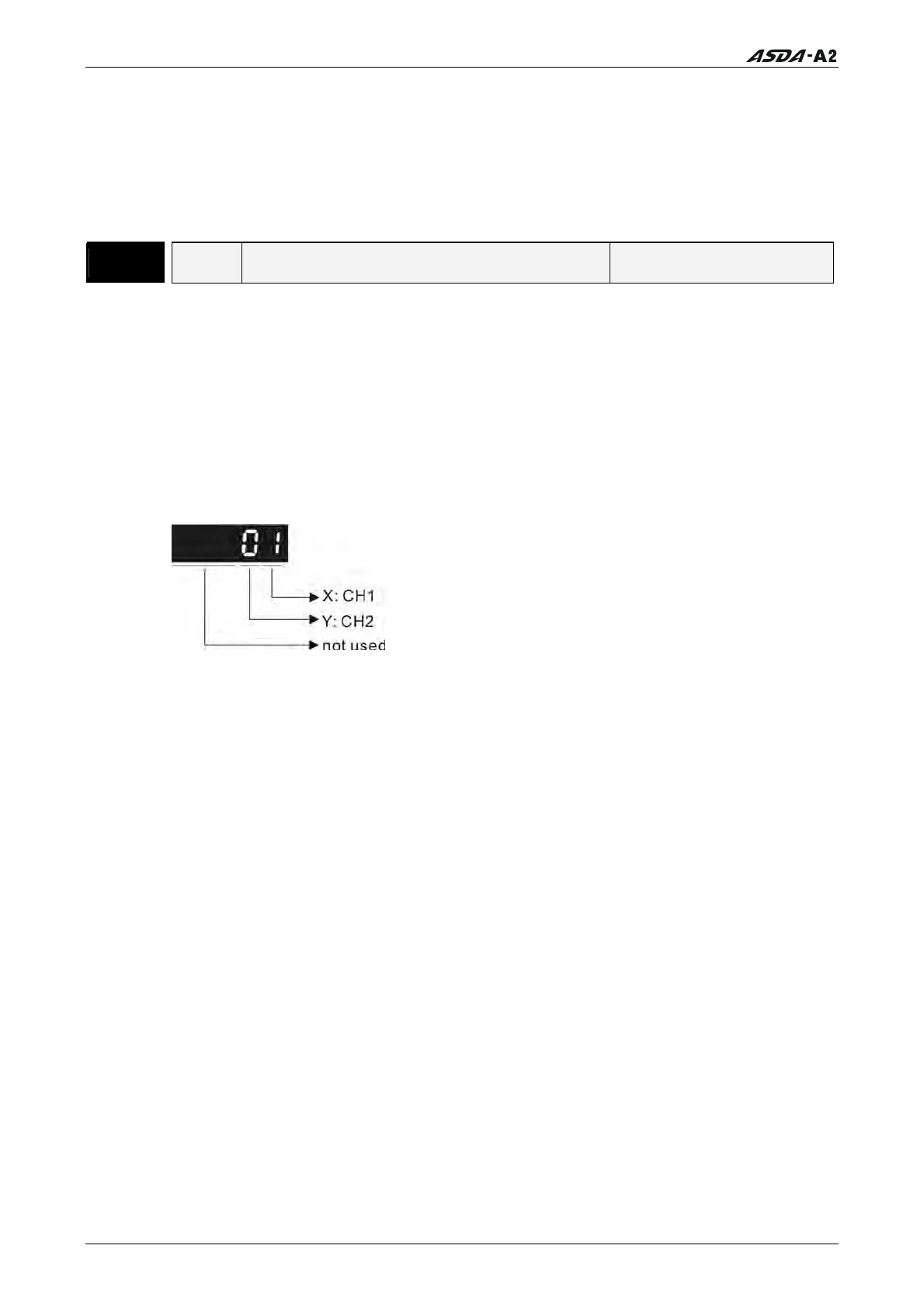
This parameter determines the functions of the analog monitor outputs.
XY: (X: CH1; Y: CH2)
0: Motor speed (+/-8V / maximum motor speed)
1: Motor torque (+/-8V / maximum torque)
2: Pulse command frequency (+8Volts / 4.5Mpps)
3: Speed command (+/-8Volts / maximum speed command)
4: Torque command (+/-8Volts / maximum torque command)
5: V_BUS voltage (+/-8Volts / 450V)
6: Reserved
7: Reserved
Please note: For the setting of analog output voltage proportion, refer to the P1-04
and P1-05.
Example:
P0-03 = 01(CH1 is speed analog output)
Motor speed = (Max. motor speed × V1/8) × P1-04/100, when the output voltage
value of CH1 is V1.
6-54 Revision January 2011
Call 1(800)985-6929 for Sales
Call 1(800)985-6929 for Sales