Chapter 8 Servo Parameters
Revision January 2011 8-33
01: Input pulse number of pulse command (after electronic gear ratio is set) [user unit]
02: Position error counts between control command pulse and feedback pulse [user
unit]
03: Motor feedback pulse number (encoder unit, 1280000 pulse/rev) [pulse]
04: Input pulse number of pulse command (before electronic gear ratio is set) [pulse]
05: Position error counts [pulse]
06: Input frequency of pulse command [Kpps]
07: Motor rotation speed [r/min]
08: Speed input command [Volt]
09: Speed input command [r/min]
10: Torque input command [Volt]
11: Torque input command [%]
12: Average load [%]
13: Peak load [%]
14: Main circuit voltage [Volt]
15: Ratio of load inertia to Motor inertia [0.1times]
16: IGBT temperature
17: Resonance frequency [Hz]
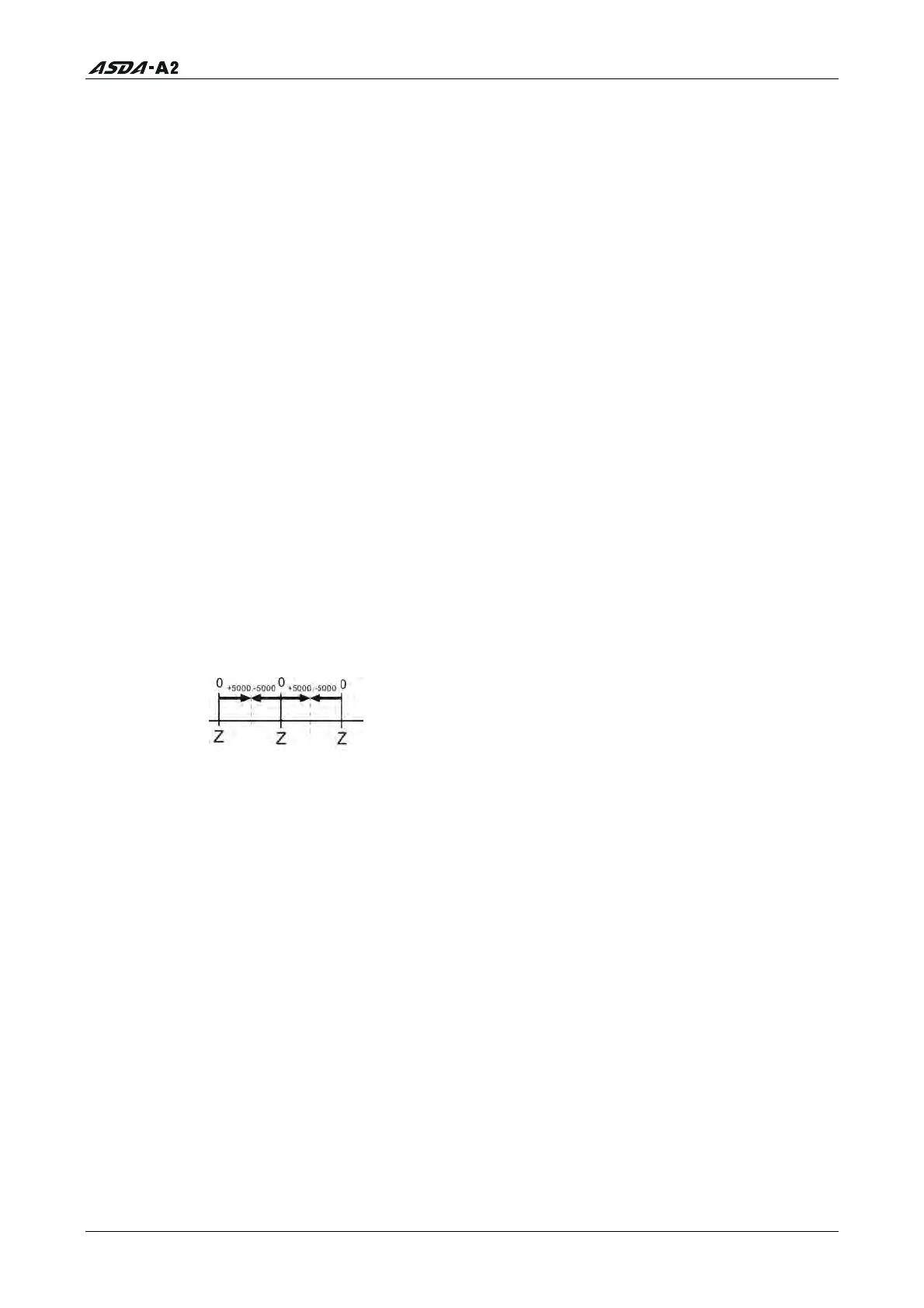
18: Absolute pulse number relative to encoder (use Z phase as home). The value of Z
phase home point is 0, and it can be the value from -5000 to +5000 pulses.
19: Mapping Parameter 1: Display the content of parameter P0-25 (mapping target is
specified by parameter P0-35)
20: Mapping Parameter 2: Display the content of parameter P0-26 (mapping target is
specified by parameter P0-36)
21: Mapping Parameter 3: Display the content of parameter P0-27 (mapping target is
specified by parameter P0-37)
22: Mapping Parameter 4: Display the content of parameter P0-28 (mapping target is
specified by parameter P0-38)
23: Status Monitor 1: Display the content of parameter P0-09 (the monitor status is
specified by parameter P0-17)
24: Status Monitor 2: Display the content of parameter P0-10 (the monitor status is
specified by parameter P0-18)
25: Status Monitor 3: Display the content of parameter P0-11 (the monitor status is
specified by parameter P0-19)
26: Status Monitor 4: Display the content of parameter P0-12 (the monitor status is
specified by parameter P0-20)
Call 1(800)985-6929 for Sales
Call 1(800)985-6929 for Sales