Chapter 8 Servo Parameters
Revision January 2011 8-81
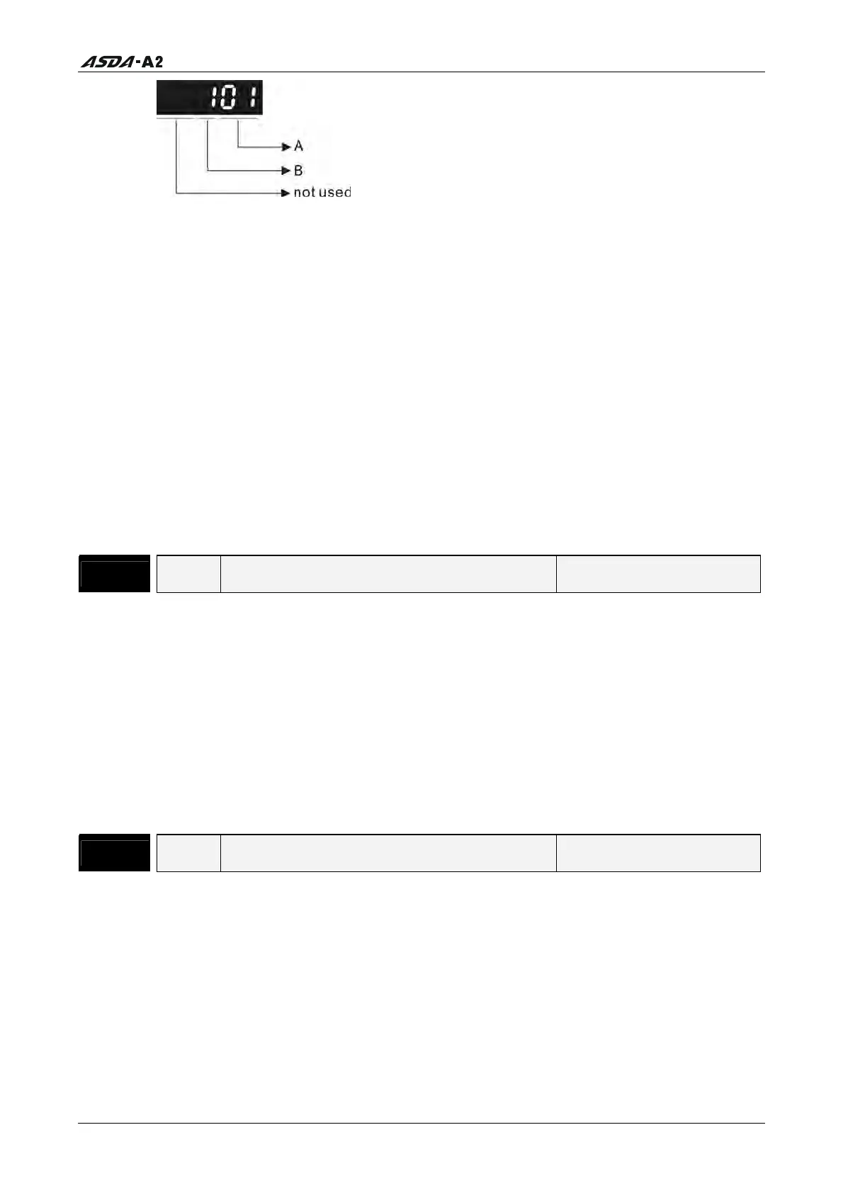
A: DI (Digital Input) Function Settings:
For the setting value of P2- 10 ~ P2-17, please refer to Table 8.A.
B: DI (Digital Input) Enabled Status Settings:
0: Normally closed (contact b)
1: Normally open (contact a)
For example, when P2-10 is set to 101, it indicates that the function of DI1 is SON
(Servo On, setting value is 0x01) and it requires a normally open contact to be
connected to it.
Please re-start the servo drive after parameters have been changed.
Please note:
The parameter P3-06 is used to set how the Digital Inputs (DI) accept commands and
signals through the external terminals or via the communication which is determined
by parameter P4-07.
P2 - 11
DI2 Digital Input Terminal 2 (DI2) Address: 0216H, 0217H
Default: 104 Related Section: Table 8.A
Applicable Control Mode: ALL
Unit: N/A
Range: 0 ~ 015Fh
Data Size: 16-bit
Display Format: Hexadecimal
Settings:
Refer to P2-10 for explanation.
P2 - 12
DI3 Digital Input Terminal 3 (DI3) Address: 0218H, 0219H
Default: 116 Related Section: Table 8.A
Applicable Control Mode: ALL
Unit: N/A
Range: 0 ~ 015Fh
Data Size: 16-bit
Display Format: Hexadecimal
Settings:
Refer to P2-10 for explanation.
Call 1(800)985-6929 for Sales
Call 1(800)985-6929 for Sales