Chapter 8 Servo Parameters
Revision January 2011 8-87
A: Gain Switching Condition Settings:
0: Disabled
1: Gain switching DI (Digital Input) signal (GAINUP) is On. (see Table 8.A)
2: In position mode, position deviation is higher than the setting value of P2-29.
3: Position command frequency is higher than the setting value of P2-29.
4: Servo motor speed is higher than the setting value of P2-29.
5: Gain switching DI (Digital Input) signal (GAINUP) is Off. (see Table 8.A)
6: In position mode, position deviation is lower than the setting value of P2-29.
7: Position command frequency is lower than the setting value of P2-29.
8: Servo motor speed is lower than the setting value of P2-29.
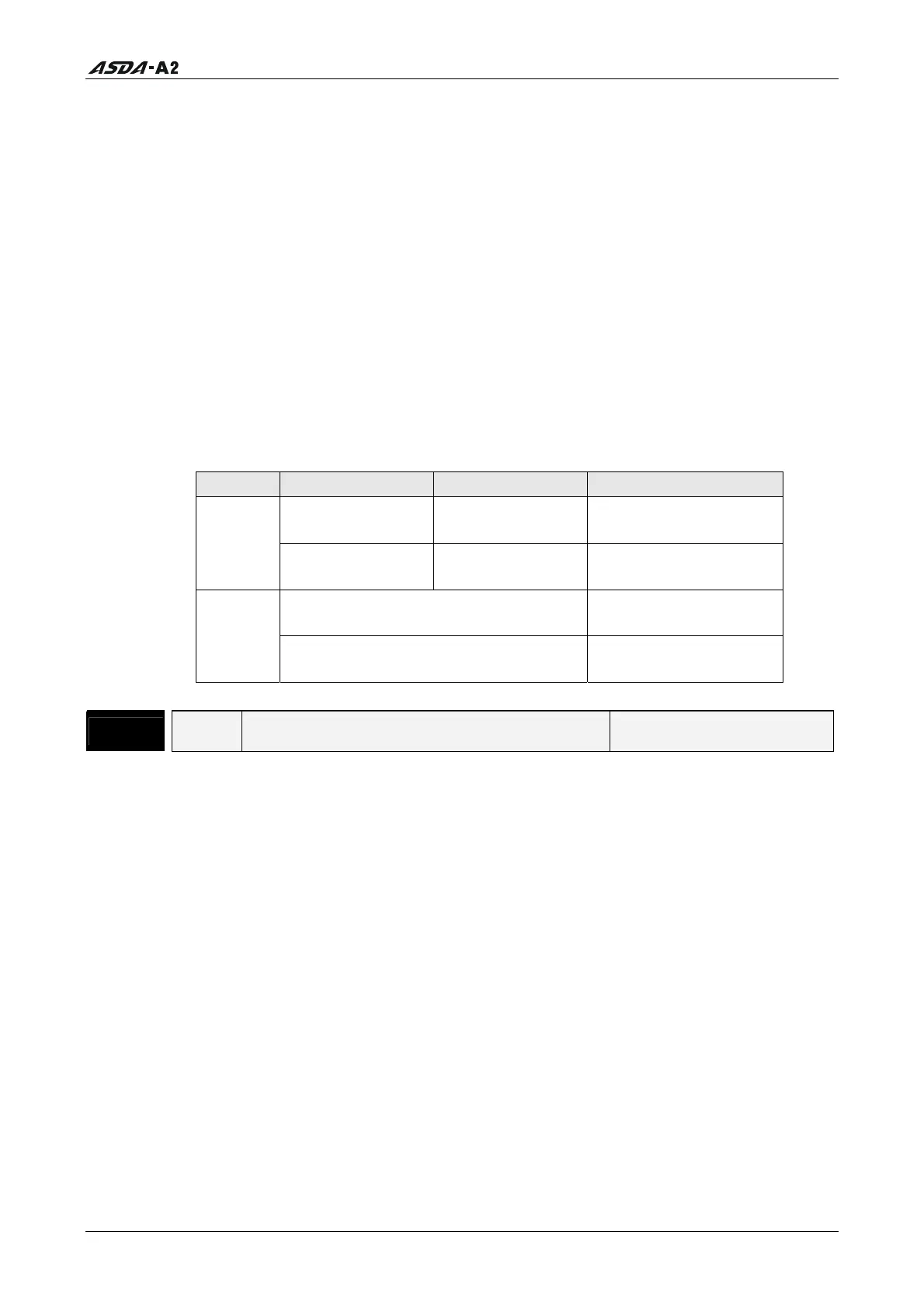
B: Gain Switching Control Settings:
0: Gain multiple switching
1: P PI switching
Setting P mode S mode Status
P2-00 x 100%
P2-04 x 100%
P2-04 x 100% Before switching
0
P2-00 x P2-01
P2-04 x P2-05
P2-04 x P2-05 After switching
P2-06 x 0%
P2-26 x 0%
Before switching
1
P2-06 x 100%
P2-26 x 100%
After switching
P2 - 28
GUT Gain Switching Time Constant Address: 0238H, 0239H
Default: 10 Related Section: N/A
Applicable Control Mode: ALL
Unit: 10msec
Range: 0 ~ 1000
Data Size: 16-bit
Display Format: Decimal
Settings:
This parameter is used to set the time constant when switching the smooth gain.
If P2-28 is set to 0, this parameter is disabled.
Call 1(800)985-6929 for Sales
Call 1(800)985-6929 for Sales