- 3 -
Output Point
Inductive
#3
12W (24VDC)
Lamp 20WDC/100WAC 2W(24VDC)
Off ĺ On 2ȝs 20ȝs 100ȝs
Response time
On ĺ Off
Approx .10ms
3ȝs 30ȝs 100ȝs
#1: Please refer to “I/O Terminal Layout” for the max. X/Y No. on each model.
#2: UP, ZP must work with external auxiliary power supply 24VDC (-15% ~ +20%), rated
consumption approx. 1mA/point.
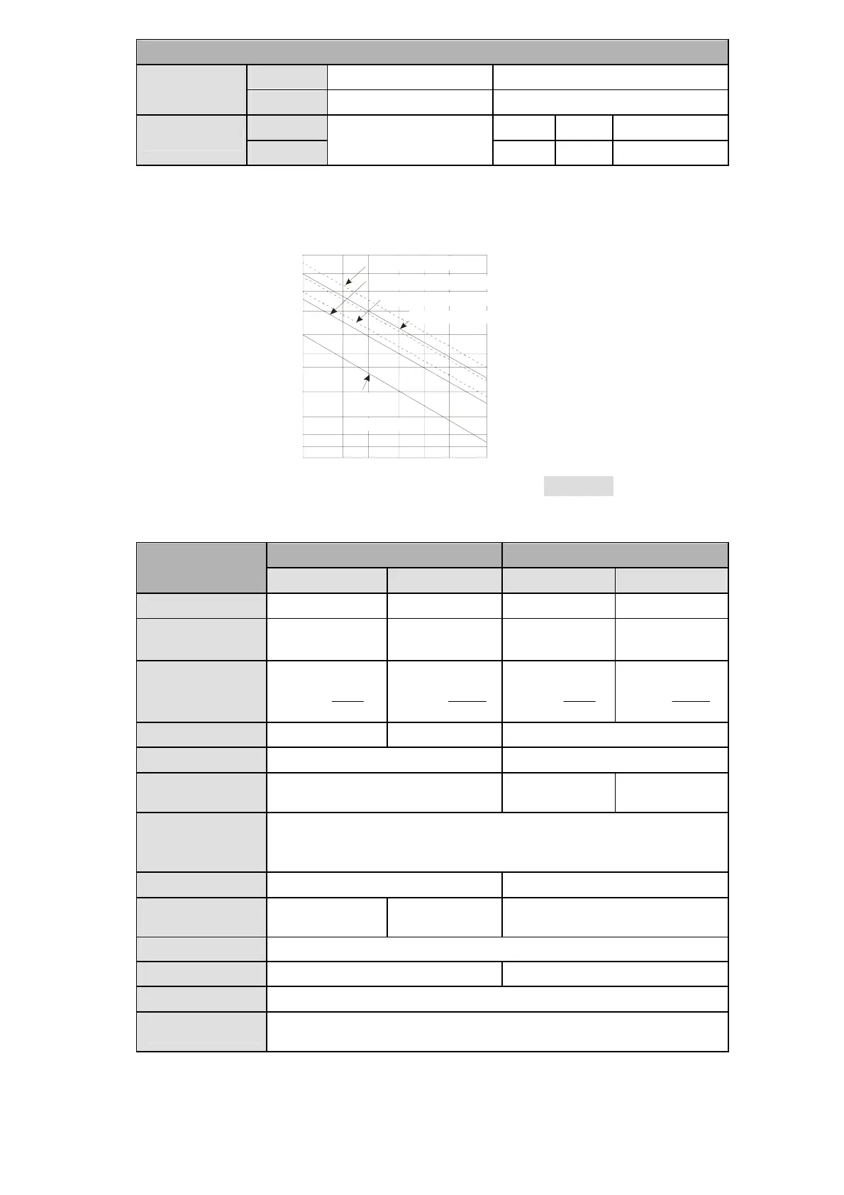
#3: Life curves
Contact Current(A)
20
0.5
0.1
0.2
30
50
0.3 0.7 1 2
200
300
500
100
1,000
2,000
3,000
O
p
e
r
a
t
i
o
n
(
X
1
0
)
3
120VAC Resistive
30VDC Inductive(t=7ms)
240VAC Inductive(cos 0.4)
ӿ
=
120VAC Inductive(cos =0.4)
ӿ
30VDC
Inductive
(t=40ms)
[ Figure 3 ]
A/D and D/A Specifications (For EX2 Model Only)
Analog Input (A/D) Analog Output (D/A)
Items
Voltage input Current input Voltage output Current output
Analog I/O range ±10V ±20mA ±10V 0 ~ 20mA
Digital conversion
range
-2,000 ~ +2,000 -2,000 ~ +2,000 -2,000 ~ +2,000 0 ~ +4,000
Resolution
12-bit
)
4000
20V
5mV(
12-bit
)
4000
40mA
ȝǹ(10
12-bit
)
4000
20V
5mV(
12-bit
)
4000
20mA
ȝǹ(5
Input impedance > 1Mȍ 250ȍ -
Output impedance - 0.5ȍ or lower
Tolerance carried
impedance
- > 5Kȍ < 500ȍ
Overall accuracy
Non-linear accuracy: ±1% of full scale within the range of PLC operation
temperature
Maximum deviation: r1% of full scale at 20mA and +10V
Response time 2ms (set up in D1118)
#1
2ms
#2
Absolute input
range
±15V ±32mA -
Digital data format
2’s complement of 16-bit, 12 significant bits
Average function Provided (set up in D1062)
#3
-
Isolation method No Isolation between digital circuit and analog circuit
Protection
Voltage output has short circuit protection, but a long period of short
circuit may cause internal wire damage and open circuit of current output.
#1: When the scan period is longer than 2ms or the set value, the setting will follow the scan
period.
#2: When the scan period is longer than 2ms, the setting will follow the scan period.
#3: When the sampling range is “1”, the present value will be read.
 Loading...


