- 5 -
3. Output terminals, Y0 ~Y5 of transistor models use UP, ZP common port. See [Figure
8].
4. Isolation circuit: The optical coupler is used to isolate signals between the circuit
inside PLC and input modules.
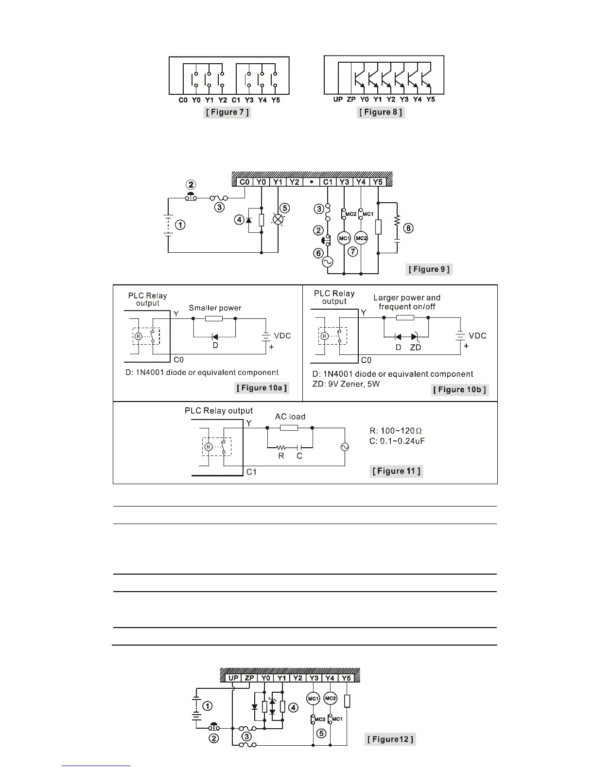
Relay (R) output circuit wiring
c
DC power supply
d
Emergency stop: Uses external switch
e
Fuse: Uses 5~10A fuse at the shared terminal of output contacts to protect the output circuit
f
Transient voltage suppressor (SB360 3A 60V): Extends the life span of contact.
1. Diode suppression of DC load: Used when in smaller power [Figure 10a]
2. Diode + Zener suppression of DC load: Used when in larger power and frequent On/Off
[Figure 10b]
g
Incandescent light (resistive load)
h
AC power supply
i
Manually exclusive output: For example, Y3 and Y4 control the forward running and reverse
running of the motor, forming an interlock for the external circuit, together with the PLC
internal program, to ensure safe protection in case of any unexpected errors.
j
Absorber: Reduces the interference on AC load [Figure 11]
Transistor (T) output circuit wiring