- 6 -
c
DC power supply
d
Emergency stop
e
Circuit protection fuse
f
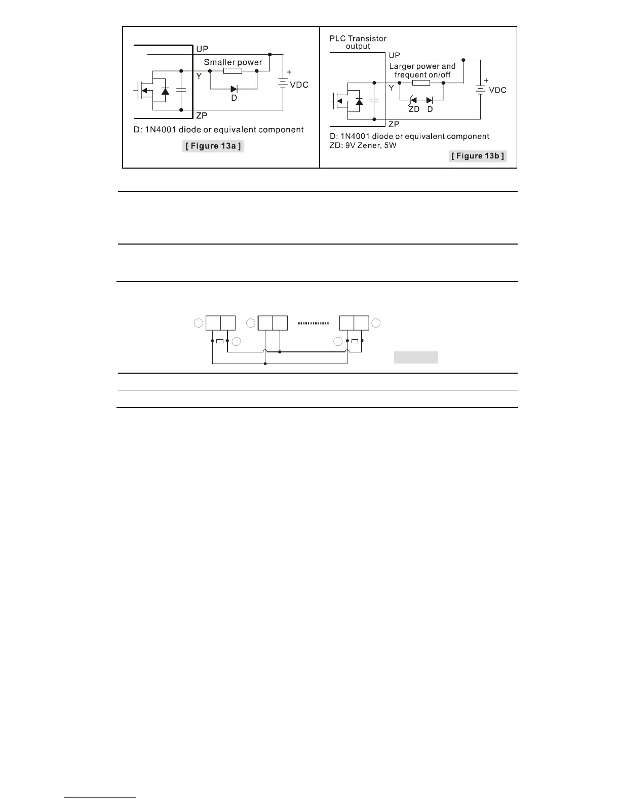
The output of the transistor model is “open collector”. If Y0/Y1 is set to pulse output, the
output current has to be bigger than 0.1A to ensure normal operation of the model.
1. Diode suppression: Used when in smaller power [Figure 13a]
2. Diode + Zener suppression: Used when in larger power and frequent On/Off [Figure 13b]
g
Manually exclusive output: For example, Y3 and Y4 control the forward running and reverse
running of the motor, forming an interlock for the external circuit, together with the PLC
internal program, to ensure safe protection in case of any unexpected errors.
RS-485 Wiring
Figure 14
D+ D- D+ D- D+ D-
3
1 2 2
3
c
Master node
d
Slave node
e
Terminal resistor
Note: 1. Terminal resistors are suggested to be connected to master and the last slave with
resistor value of 120Ω.
2. To ensure communication quality, please apply double shielded twisted pair cable
(20AWG) for wiring.