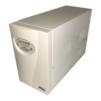
11
3-3 Installation
Notice:
- AC output need a disconnect device such as a breaker which has to be
provided by others.
- The wire length of output power cord connected to the output receptacle
or pressure terminal should be less then 10 meters.
- The UPS provide with pressure terminal connector for field installed
wiring, the terminal connector should be applied a 13.8 lb-in (1.554 N-m)
of tightening torque.
- The over current protection and short circuit protection for the AC output
is provided by internal circuits of UPS and breaker.
- Concerning about the battery voltage, ambient temperature and other
specifications of the UPS, please refer to the specification section of this
manual.
- Servicing of batteries should be performed or supervised by personnel
knowledgeable of batteries and the required precautions. Keep unauthorized
personnel away batteries.
- When replacing batteries, replace with the same type and number.
1. Connecting to utility power (Refer to Fig 3-3)
- Connect the BS546 plug of power cord to the BS546 connector on the
UPS.
- Plug the other end of the power cord into a two-pole, three-wire,
grounding receptacle only. Avoid using extension cords and adapter
plug.
- Turn on the input breaker (if the breaker can be turned on) on the rear
panel of UPS.
- After that, the fan (in rear panel) will run and all LEDs will light for about
2-3 sec. Meanwhile the CPU inside the UPS setups the initial
parameters. User also can check whether all LEDs are normal or not.
The UPS is set in “STANDBY mode” initially, after a ‘bee’ is heard, the
load LED lights on and the line LED shows AC utility status. Shown as fig
3-1.