21
1
2345
6789
8. COMMUNICATION INTERFACE
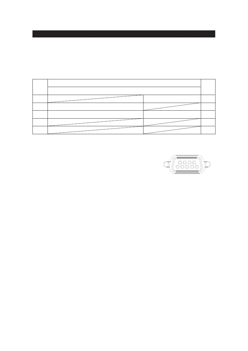
The UPS provides RS-232 protocols in one D-sub 9 connector. Using proper UPS
management software and cable, the UPS can be managed over
LAN/intranet/internet environment. The pin assignment of the D-sub 9 connector
is defined as follows:
8-1 RS-232
Pin2 : PC receives line RS-232 data from UPS.
Pin3 : PC transmits line RS-232 data to UPS.
Pin5 : Signal ground.
Pin7 : Reversed for plug and play function.
The RS-232 communication port provides the following functions:
1) Monitoring charger status
2) Monitoring battery status and condition
3) Monitoring inverter status
4) Monitoring UPS status
5) Monitoring the utility status
6) Providing the power switch function for computer to turn on/off the utility
on schedule for power saving
7) Adjustable Transfer voltage
The UPS data is provided at 2400 bps baud rate and made up of 8-bit, 1 stop-bit
and no parity bit. All information is encoded in ASCII format.
HARDWARE:
- BAUD RATE--------------2400 bps - DATA LENGTH----------8 bits
- PARITY--------------------NONE - STOP BIT-----------------1 bit
CABLING:Standard D-sub 9 cable (UPS side: male, PC side: female)
ASSIGNMENT DESCRIPTION
PIN
RS-232
PIN
1 GND 5
2 UPS TxD(typical RS-232 level) 6
3 UPS RxD(typical RS-232 level) Reserved for PNP 7
4 8
9
Fig 8-1 Pin Assignment