GENERAL ES300
6 / 13 DELTA ELEKTRONIKA B.V. rev. Sept. 2019
2.16
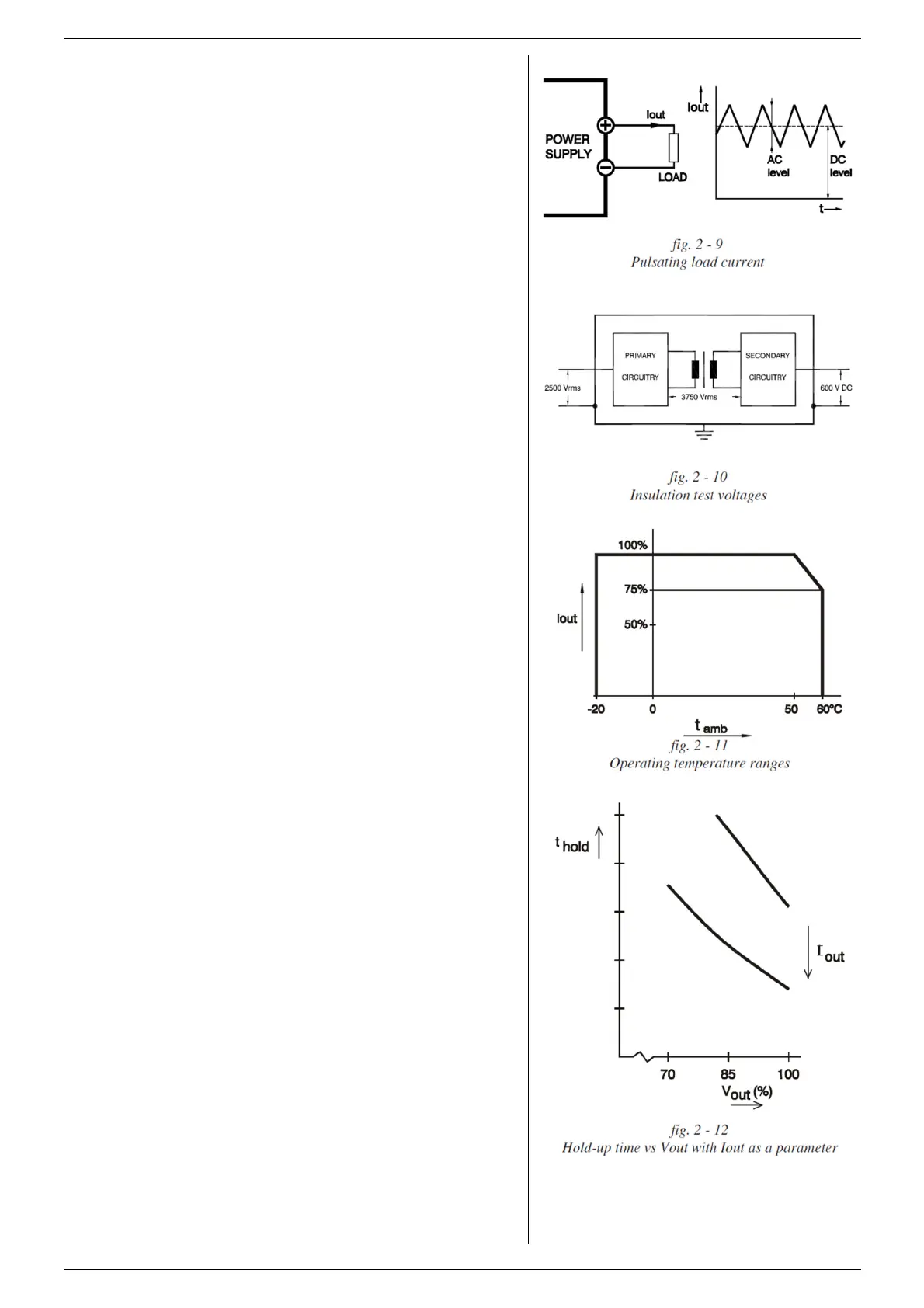
PULSATING LOAD
To avoid overheating the output capacitors, the AC
component of the load current should be limited (fig. 2 - 9).
One method of decreasing the AC current through the output
capacitor is by using a large external electrolytic capacitor in
parallel with the load.
Care must be taken so that the capacitor in combination with
the lead inductance will not form a series resonant circuit!
2.17
INSULATION
For safety the insulation of the separating components
(transformers) between input and output is tested at 3750
Vrms during 1 minute. This is tested before assembling.
Warning! The 3750 Vrms cannot be tested afterwards on the
assembled unit because the insulation between the
components on the input side to the case (like the bridge
rectifier) is specified at 2500 Vrms. Since the insulation output
- case is low (only 600 VDC) the insulation of the primary
components to case will break down when 3750 Vrms is
applied between input and output (2500 Vrms + 600 VDC <
3750 Vrms) (see also fig. 2 - 10).
Note: when testing the insulation, take care to charge and
discharge the capacitors between input - case and output -
case slowly (e.g. in one second). This to pevent high peak
currents, which could destroy the power supply. Make sure to
have discharged the capacitors completely before using it
again.
2.18
RFI SUPPRESSION
Both the input and output have RFI filters, resulting in very
low conducted RFI to the line and load. Due to the output filter
the output voltage is very clean, having almost no spikes.
The combination of RFI filters and the closed metal case
results in a low radiated RFI.
2.19
OPERATING TEMP
At full power the operating temperature range is –20 to
+50 °C. From 50 to 60 °C the output current has to be derated
linearly to 75 % at 60 °C (see fig. 2 - 11). These temperatures
hold for normal use.
2.20
THERMAL PROTECTION
A thermal switch shuts down the output in case of insufficient
cooling. After cooling down the unit will start working again.
2.21
HOLD - UP TIME
The hold - up time depends on the load, output voltage and
line input voltage. A lighter load or a lower output voltage
results in a longer hold - up time (see fig. 2 - 12). The
influence of the line input voltage is limited because of the
active PFC.
2.22
TURN ON DELAY
The output voltage is available 0.25 sec after mains switch
on.
2.23
INRUSH CURRENT
The inrush current is limited with a 16 Ohm NTC to about 10
A when the NTC is cold.
2.24
COOLING
The cooling is by natural convection, no noisy blowers are
present. The unit should have sufficient free space to let the
air flow vertically through the unit. A distance of minimum 5
cm around the unit is recommended.
For long life the temperature of the air entering the unit,
should be below 35 °C under normal conditions.
Under extreme conditions it should be below 50 °C.

 Loading...


