DELTA ELEKTRONIKA BV M - SERIES
Page 1 - 4 Febr. 2005
SPECIFICATIONS
Input voltage
110 - 120 - 230 - 240 V 48/62 Hz
(by changing transformer taps).
Input current (230 V)
Half rack model 2.2 A, full rack 3.5 A
Fuses, 5 x 20 mm, slow blow
Half rack: 4 A T at 230 V, 6.3 A at 110 V
Full rack: 6.3 A T at 230 V, 10 A at 110 V
Power factor 0.8
Insulation
Input to output: 4 kV RMS
Input to case: 2500 V RMS
Output to case: 500 V DC
The transformer has a split bobbin according to VDE
0551, CEE 15 which makes the unit very safe.
Safety EN 60950, EN 61010
SELV/PELV (for M15-16HE, M24-12HE,
M24-20HE)
EMC
EN 61204-3
EN 61000-6-3 (EN55022B)
EN 61000-6-2
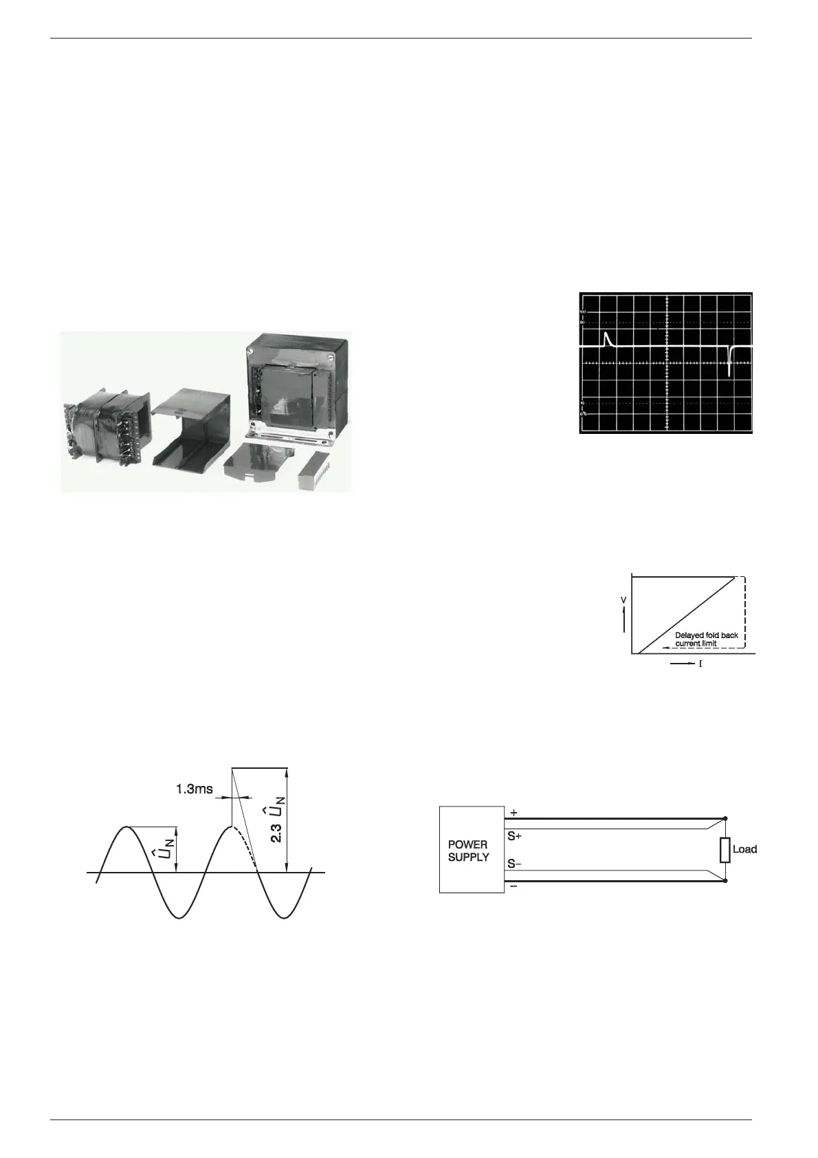
VDE 0160 impulse test
The M-units withstand the high energy impulse test
2.3 Û
N
1.3 ms of VDE 0160 class 2
Hold-up time (230 V input)
24 V units 20 ms at full and 50 ms at half load. Other
models 15 ms at full and 30 ms at half load.
Voltage regulation
0.02% for a +10% to –10% line variation.
0.02% for a 0-100% load change.
Ripple + noise
0.2 mVrms (BW = 300 kHz)
5 mVp-p (BW = 50 MHz)
Temperature coeff.
0.01% per °C
Drift
Less than 0.1% per 8 hours under constant ambient
and load conditions after 1 hour warm-up.
Output impedance
Less than 0.1 Ohm at 0 to 100 kHz load frequency.
Recovery time
25 us for recovery to within 30 mV of steady state volt-
age after a step load change from 10% to 100%. Max.
deviation: Less than
0.25 V
Recovery time:
M 24-12 HE
Hor.: 100 us/div.
Vert.: 0.1 V/div.
Current limit
The linear M-models have a fold back overload char-
acteristics (a constant cur-
rent characteristic would
overheat the series pass
transistors when the output
is short circuited).
A ‘delayed fold back’ is used
to avoid problems during
switching-on of series con-
nected power supplies or
non linear loads. The current limit is adjustable from
about 40 to 100% of the rated current.
Remote sensing
Remote sensing at the load point can be used to com-
pensate for the voltage drop across the load leads.
Max. 2 V per load lead can be compensated. The
voltage across the output will rise accordingly, which
will limit the max. AC input voltage swing (check
graphs on next page). Also the OVP has to be set
higher. The output is protected against accidental in
-
terruption or reversing of the sense leads.
A capacitor of 1000 uF across the load can be usefull
to lower the impedance caused by long load leads.
 Loading...


