TROUBLE SHOOTING SM1500
Page 5 - 2 DELTA ELEKTRONIKA B.V. rev. August 2018
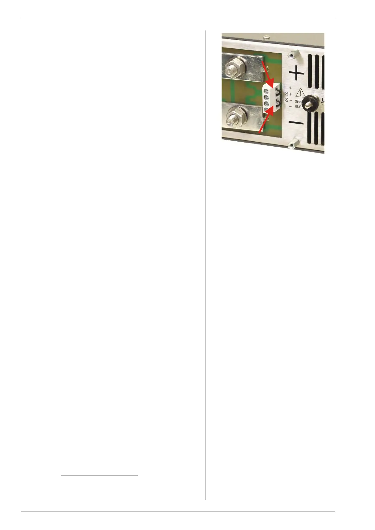
fig. 5 - 3
For nor mal op er a tion links should be con nected
be tween S+ and + and be tween S– and –
6 MAS TER / SLAVE PAR AL LEL PROB LEMS
• Check the volt age drop of the wir ing be tween the mas ter and the
slaves is < 10 mV.
• Check the wir ing has a low in duc tance.
7 OUT PUT VOLT AGE IS HIGHER THAN SET VALUE
• Check con nec tions on SENSE BLOCK (on rear panel), For nor -
mal op er a tion there should be a link be tween + and S+ and be -
tween – and S– (see also fig. 5 - 3). When re mote sens ing is used,
check the wires of the sens ing.
8 OT LED on
• The tem per a ture of the in ter nal heat sink is too high,
the out put has been shut down to avoid over heat ing.
• Check if the cool ing fan is run ning.
• Check if the air tem per a ture of the air in let (left) is be low 50 °C and
the air flow is not ob structed.
9 OT LED blinks
• The tem per a ture of the in ter nal heat sink is get ting too high, a fur -
ther in crease will shut down the power sup ply.
• Check if the cool ing fan is run ning prop erly.
• Check if the air tem per a ture of the air in lets (left) is be low 50 °C
and the air flow is not ob structed.
10 ACF LED on
• The in put volt age is too low or was in ter mit tent be cause of a bad
con nec tion. Dis con nect the mains, wait a few min utes and try
again.
As soon as the ACF LED Iights, the set tings for Re mote CV, Re -
mote CC and Keylock will be saved. If the unit turns back on, it will
have the same set tings. For the set ting of Out put On/Off af ter
turn ing the unit back on, the po si tion of DIP switch 2 on SW1 is de -
ter min ing.
If the ACF sit u a tion lasts a few sec onds, the out put will shut down.
The ACF prob lem has to be solved first, be fore the out put can be
turned on again.
• In ter nal er ror, send unit for re pair. See pre vi ous para graph 1).
11 DCF LED on
• The out put volt age is be low the set volt age. This au to mat i cally
hap pens when the unit is in CC-mode (CC LED is on).
Also with an in ter rupted In ter lock con nec tor, the DCF LED will be
on.
• In ter nal er ror, send unit for re pair. See pre vi ous para graph 1).
12 PSOL LED on
• The Power Sink is in over load or the tem per a ture of the Power
Sink is too high. See datasheet of the Power Sink op tion for fur -
ther de tails.
13 NO LEDS on
• Check in put.
• Do not try to re pair, but send for re pair. See pre vi ous para graph
1).
14 Blink ing LEDs RE MOTE CV, RE MOTE CC and
OUT PUT ON
• This in di cates the Keylock func tion is ac ti vated, see pre vi ous
para graph 5) in "op er at ing man ual".
15 OTHER
• If the prob lem per sists, please fill out the RMA-form on our
website www.DeltaPowerSupplies.com
. See pre vi ous para graph
1).

 Loading...