SM1500 GENERAL
rev. August 2018 DELTA ELEKTRONIKA B.V. Page 3 - 1
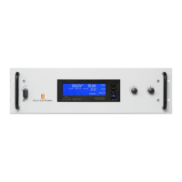
fig. 3 - 1
Out put ranges. Ev ery point in hatched
area can be used.
SM 300-5
SM 120-13
SM 35-45
SM 52-30
SM 70-22
SM 52-AR-60
SM 15-100
3 GENERAL
1) OUT PUT
The SM15-100, SM35-45, SM52-30, SM52-AR-60, SM70-22, SM120-13,
SM300-5 and the SM400-AR-8 can ei ther be used as a con stant volt age
source with cur rent lim it ing or as a con stant cur rent source with volt age lim it -
ing. The change of mode oc curs sharply at the cross ing of the volt age and
cur rent set tings. Fig. 3 - 1 shows the out put ranges.
The SM52-AR-60 and the SM400-AR-8 fea ture an AUTORANGING fa cil ity
where the power sup ply au to mat i cally switches over be tween two cur rent
ranges. This switch ing, which is un no tice able for the user, re sults in a ver sa -
tile power sup ply with twice the out put voltage range. This means that for
the SM52-AR-60 the max i mum out put power of 1560 W is avail able at both
26 V and 52 V. For the SM400-AR-8 this is 1600 W at both 200 V and 400 V.
° DIS PLAY CV/CC SETTINGS FUNCTION
The set tings of the volt age and cur rent con trol (also when pro grammed) can
be ob served on the front panel me ters by press ing the Dis play CV/CC Set -
tings but ton. This al lows the cur rent limit to be set when op er at ing in the CV
mode with out short ing the out put ter mi nals, and the volt age limit to be set
when op er at ing in the CC mode with out open ing the load leads.
° OVER LOAD PRO TEC TION
The power sup ply is fully pro tected against all over load con di tions, in clud ing
short cir cuit.
2) IN PUT VOLT AGE
The power sup plies have a wide in put volt age range.
° At line volt ages be low about 120 V AC the out put power has to be de rated,
see page 1-2, "In put".
3) IN PUT CUR RENT
The unit has ac tive power fac tor cor rec tion (PFC). The in put cur rent will
there fore al most be a sine wave. This means that the RMS-value and the
har monic dis tor tion of the in put cur rent will be rel a tively low.
4) STANDBY IN PUT POWER
The unit con sumes very lit tle power when in standby. This makes it pos si ble
to leave the in put power on when the out put is dis abled us ing the Out put
On/Off func tion (push but ton on front panel) or the Re mote Shut Down in put
(pin 5 on con nec tor CON E on the rear panel).
5) EFFICIENCY
The ef fi ciency is very high and con stant over a wide out put cur rent range.
High ef fi ciency means low power loss and low heat gen er a tion.
6) CV REG U LA TION
The CV-load reg u la tion should be mea sured di rectly on the out put ter mi nals
be cause a few cm of ca ble can have a volt age drop of sev eral mV (at high
cur rent!).
7) CC REG U LA TION
For ac cu rate CC-load reg u la tion, do not use ex ter nal volt age sens ing.
A volt age be tween S- and mi nus out put will cre ate an er ror of about 0.04 %
per volt.
A volt age be tween S+ and + is not crit i cal.The CC-stability is also af fected by
ex ter nal volt age sens ing.
Note: when the unit op er ates in CC-mode, the DCF-LED will be on. When
the unit is in CC-mode most of the time, it is pos si ble to dis able the LED with
DIP switch 3 on SW1 (rear panel).
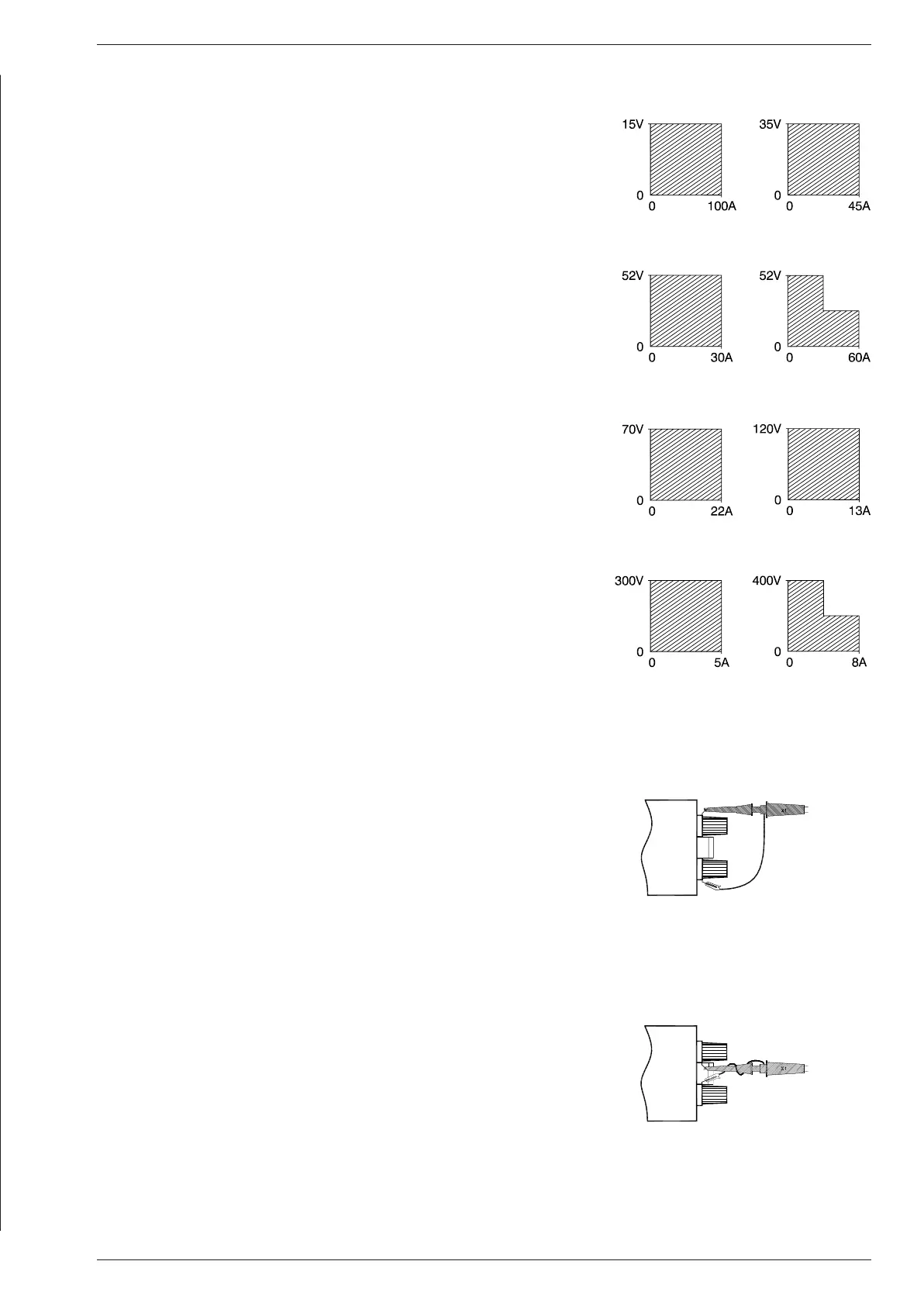
8) RIP PLE & NOISE
The out put rip ple is very low with al most no spikes. The rip ple volt age has to
be mea sured di rectly on the out put ter mi nals us ing a probe with very short
con nec tions (to avoid pick up of mag netic fields (see fig. 3 - 2 and fig. 3 - 3).
At low tem per a tures like −20°C the rip ple in creases. By us ing high qual ity
elec tro lytic ca pac i tors the in crease is rel a tively low.
fig. 3 - 2
Mea sur ing rip ple volt age
WRONG !
fig. 3 - 3
Mea sur ing rip ple volt age
RIGHT !
SM 400-AR-8

 Loading...