SM6000 INSTALLATION
rev. June 2018 DELTA ELEKTRONIKA B.V. Page 4 - 4
• Pro tec tive mea sures
Use a CIR CUIT BREAKER in se ries in or der to pro tect the power
sup ply from ac ci den tal re verse con nec tion (see fig. 4 - 8).The
cir cuit breaker should have a DC volt age rat ing twice the bat tery
volt age. Use the very fast type (Z), a type meant for pro tect ing
semi con duc tors (see ta ble 4 - 2).
The unit has a re verse di ode in par al lel with the out put, this di ode
and the wir ing can not with stand the thou sands of am peres sup -
plied by a wrongly con nected bat tery.
14) RE MOTE SHUTDOWN
• The Re mote ShutDown can be op er ated on CON E by a
volt age of +4 V...+12 V or by a re lay con tact be tween Vref and Re -
mote Shut Down (pin 9 and 5) (see fig. 4 - 9).
• When the unit is pro grammed with an op tional PSC, a
soft ware com mand can be used for Re mote Shut down.
• In the Re mote ShutDown con di tion, the RSD LED will light.
The DCF LED, DCF sta tus and the DCF re lay will be off.
Im por tant: If the link from the In ter lock con nec tor (CON A) has
been re moved, the RSD LED will be on, but in this con di tion also
the DCF LED, the DCF sta tus and the DCF re lay will be on.
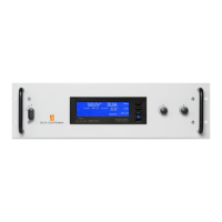
15) MASTER / SLAVE SERIES OP ER A TION
• Con nect out put ter mi nals and test sys tem in nor mal
se ries op er a tion. En sure that all (out put) power con nec tions are
re li able.
• The volt age drop in the con nect ing leads be tween the units
should be kept < 10 mV.
• Switch off all units. Con nect units as shown in fig. 4 - 10.
To con nect the slaves with the mas ter via CON B and CON C, use
stan dard UTP ca bles (RJ45).
On all units put DIP switch 4 of SW1 in po si tion DOWN to set the
units in M/S se ries mode.
• Af ter turn ing the units on again, the slaves will be in Re mote CV
mode and the Key lock (see pre vi ous paragraph 5) is ac ti vated.
This is be cause the unit au to mat i cally de tects the pres ence of the
RJ45 con nec tor in CON C (if this ca ble is con nected to an other
unit).
If the RJ45 con nec tor is re moved from CON C when the unit is
turned on, the out put will shutdown to avoid ac ci den tal dam age.
If the ca ble is in serted when the unit is turned on, the out put shuts
down, the unit changes to Re mote CV / CC, the Key lock will be
ac ti vated and the out put will turn back on.
If DIP switch 4 of SW1 is op er ated when the unit is turned on, the
out put will shut down to avoid ac ci den tal dam age.
• The max. num ber of slaves is only lim ited by the max i mum to tal
volt age of 600 V (or 1200V for SM300-30 / SM600-10).
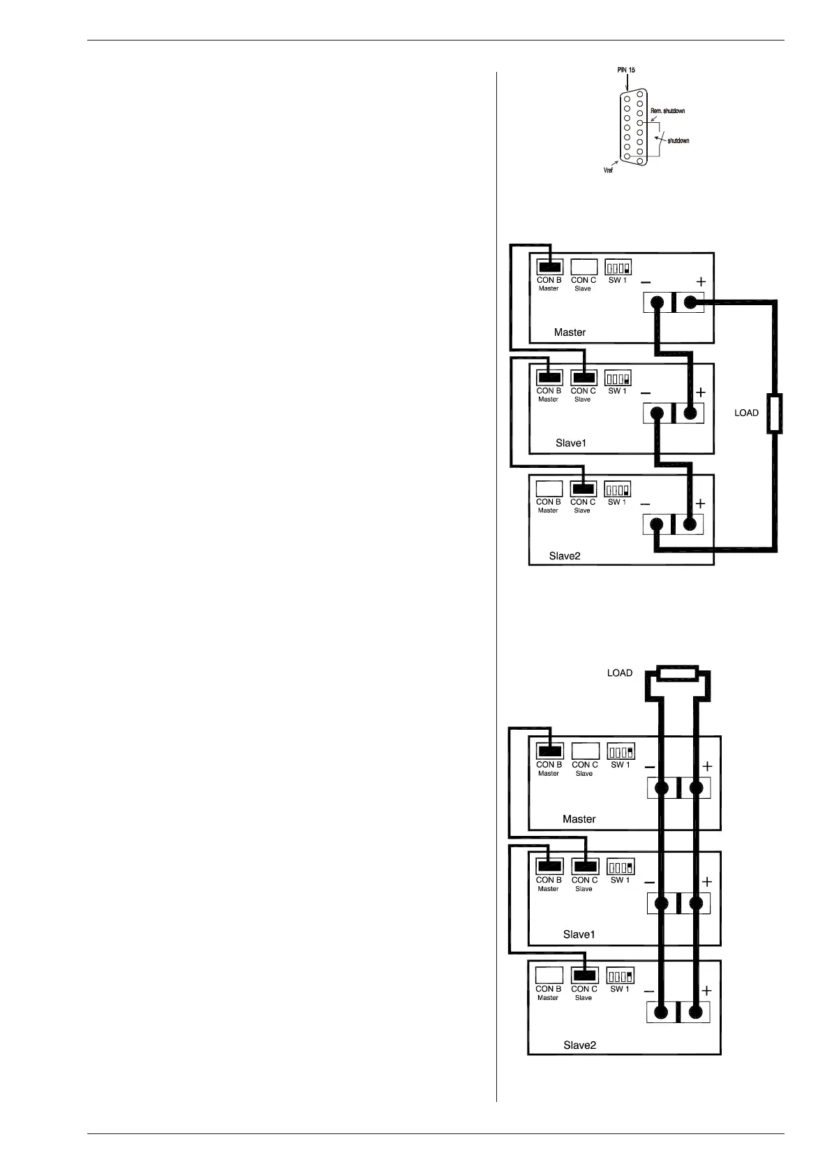
16) MASTER / SLAVE PAR AL LEL OP ER A TION
• Note: Mas ter / Slave par al lel is not rec om mended for more
than 3 units, con sult fac tory for us ing more than 3 power
sup plies in par al lel.
• First con nect out put ter mi nals and test sys tem in
nor mal par al lel op er a tion. En sure that all power
con nec tions are re li able.
• Sec ond, switch off all units. To con nect the slaves with the mas ter
via CON B and CON C, use stan dard RJ45 con nec tors ac cord ing
to fig. 4 - 11.
On all units put DIP switch 4 of SW1 in po si tion UP to set the units
in M/S par al lel mode. In this mode the DCF LED, DCF re lay and
DCF sta tus on the slaves are
dis abled be cause the slaves are al ways in CC mode.
• Af ter turn ing the units on again, the slaves will be in
Re mote CC mode and the Key lock (see pre vi ous para graph 5) is
ac ti vated. This is be cause the unit au to mat i cally de tects the pres -
ence of the RJ45 con nec tor in CON C (if this ca ble is con nected to
an other unit).
If the RJ45 con nec tor is re moved from CON C when the unit is
turned on, the out put will shut down to avoid ac ci den tal dam age.
If the ca ble is in serted when the unit is turned on, the out put shuts
down, the unit changes to Re mote CV / CC, the Key lock will be
ac ti vated and the out put will turn back on.
fig. 4 - 9 Re mote ShutDown with switch.
fig. 4 - 10
Mas ter / Slave se ries con nec tion.
fig. 4 - 11
Mas ter / Slave par al lel con nec tions.
 Loading...