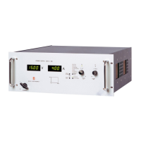
Do you have a question about the Delta Elektronika SM330-AR-22 and is the answer not in the manual?
| Model | SM330-AR-22 |
|---|---|
| Type | Programmable DC Power Supply |
| Output Current | 0-22 A |
| Input Voltage | 90-264 VAC |
| Input Frequency | 47-63 Hz |
| Storage Temperature | -20 to +70 °C |
| Protections | Over temperature |
| Operating Temperature | 0 to +50°C |
| Cooling | Forced air cooling |
General safety precautions for operation, service, and repair of the equipment.
Requirements for connecting the unit to the AC power supply mains for shock hazard minimization.
Safety considerations for grounding DC power terminals and sense connections.
Warnings about touching live parts and charged capacitors after disconnecting power.
Prohibition of opening covers and replacing components by unqualified personnel.
Safety warnings and guidelines for handling, lifting, and mounting the unit.
Information on airflow requirements, hot surfaces, and fan safety.
Step-by-step instructions for connecting AC and DC power terminals and LAN.
Guidance on initial operation, checking firmware, and performing a firmware update.
Describes the unit's ability to function as a constant voltage or constant current source.
Details the maximum output power capabilities and derating factors.
Standard availability and usage of web interface and Ethernet for programming.
Instructions and recommendations for updating the unit's firmware.
Crucial safety warnings and procedures for connecting power and other cables.
Step-by-step guide for first-time operation, controls, and modes.
Detailed configuration options for system info, front settings, protection, and interfaces.
Procedures for checking and updating the unit's firmware via the web interface.
Usage of the web interface for controlling and monitoring the unit.
Configuration settings accessible via the web interface including General, Defaults, and Sources.
Steps to diagnose and resolve issues when the unit does not provide DC output.
Troubleshooting steps for when programming commands are not functioning correctly.
Diagnosing and resolving situations where the output voltage exceeds the set value.
Troubleshooting the Over Temperature (OT) indicator and its causes.
Troubleshooting the AC Fail (ACF) indicator, related to input voltage issues.
Troubleshooting the DC Fail (DCF) indicator, related to output voltage deviations.
Troubleshooting the Power Sink Overload (PSOL) indicator.
Diagnosing internal errors and issues with interface configuration.


 Loading...