Specifications
DC Output – see Operating Instructions
QuiQ Model: 912- 24xx 36xx 48xx 72xx
Voltage-nom (V) 24 36 48 72
Voltage-max (V) 33.6 50.4 67.2 100
Current-max (A) 25 21 18 12
Battery Type Specific to selected algorithm
Reverse Polarity Electronic protection – auto-reset
Short Circuit Electronic current limit
AC Input
All models
Voltage-max (Vrms) 85 – 265
Frequency (Hz) 45 - 65
Current-max (Arms) 12A @ 104VAC (reduced 20%<104V)
Current – nominal (Arms) 10A @ 120VAC / 5A @ 230VAC
AC Power Factor >0.98 at nominal input current
Operation
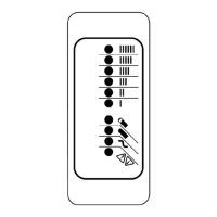
Charger Model: 912- xx0x (10 LED) xx1x (1 LED)
AC ON Solid YELLOW LED Active
AC LOW Flash YELLOW Flash YELLOW
Thermal Cutback Flash Bargraph Flash YELLOW
<80% Charge Indicator - Short Flash GREEN
>80% Charge Indicator Solid YELLOW Long Flash GREEN
100% Charge Indicator Solid GREEN Solid GREEN
Fault Indicator Flash RED Flash RED
DC Ammeter LED Bargraph -
Bat Temp Compensation Automatic Optional
Maintenance Mode Auto-restart if V<2.1Vpc or 30 days elapse
Mechanical
Regulatory
All models
Dimensions 28.0 x 24.5 x 11.0 cm (11 x 9.7 x 4.3”)
Weight <5 kg (<11 lbs) w/ standard output cord
Environmental Enclosure: IP46
Operating
Temperature
-30°C to +50°C (-22°F to 122°F), derated
above 30°C, below 0°C
Storage Temperature -40°C to +70°C (-40°F to 158°F)
AC input connector IEC320/C14 (require 1.8m localized cord)
DC output connector OEM specific w/ 12AWG wire
Safety
EN 60335-1/2-29 Safety of Appliances/ Battery Chargers
UL2202 EV Charging System Equipment
UL1564 2nd Edition Industrial Battery Charger
CSA-C22.2 No. 107.2 Battery Chargers- Industrial
Emissions
FCC Part 15/ICES 003 Unintentional Radiators Class A
EN 55011 Radio disturbance characteristics (Class A)
EN 61000-3-2 Limits for harmonic current emissions
EN 61000-3-3 Limits of voltage fluctuations and flicker
Immunity
EN 61000-4-2 Electrostatic discharge immunity
EN 61000-4-3 Radiated, radio-frequency, EMF immunity
EN 61000-4-4 Electrical fast transient/burst immunity
EN 61000-4-5 Surge immunity
EN 61000-4-6 Conducted Immunity
EN 61000-4-11 Voltage variations immunity
Installation Instructions
WARNING: The output of chargers with greater than 48V may
pose an energy and/or shock hazard under normal use. These
units must be installed in the host equipment in such a
manner that the output cable and battery connections are
only accessible with the use of a tool by qualified personnel.
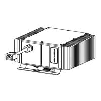
1) Determine Mounting Location:
While its sealed nature allows the charger to be mounted virtually
anywhere, the choice of mounting location and orientation is
extremely important. For optimum performance and shortest
charge times, mount the charger in an area with adequate
ventilation. The charger should also be mounted in an area that
will be relatively free of oil, dirt, mud, or dust since accumulations
within the fins of the charger will reduce their heat-dissipating
qualities. Optimal cooling also occurs when the charger is
mounted on a horizontal surface with the fins vertical. More
airflow from below the charger will help cool the fins, so mounting
above open areas or areas with cut-outs for airflow is desirable.
Contact Delta-Q for information on other mounting orientations.
As the charger may get hot in operation, the charger must be
installed such that risk of contact by people is reduced. The
charger’s AC plug must be located at least 18” above the floor/
ground surface and the status display must be visible to the user.
2) Mounting Procedure:
Mount the charger by the mounting plate using appropriate
fasteners (i.e. 1/4" or M6 with locking hardware). For UL2202
compliance, a 12AWG green bonding wire with ring terminals
must be attached from the bonding stud located on the front of the
charger (identified by ) to the vehicle frame. The vehicle
connection must be made using corrosion resistant hardware
(e.g., a #10 stainless steel machine screw with at least two
threads of engagement and, if required, a paint piercing washer).
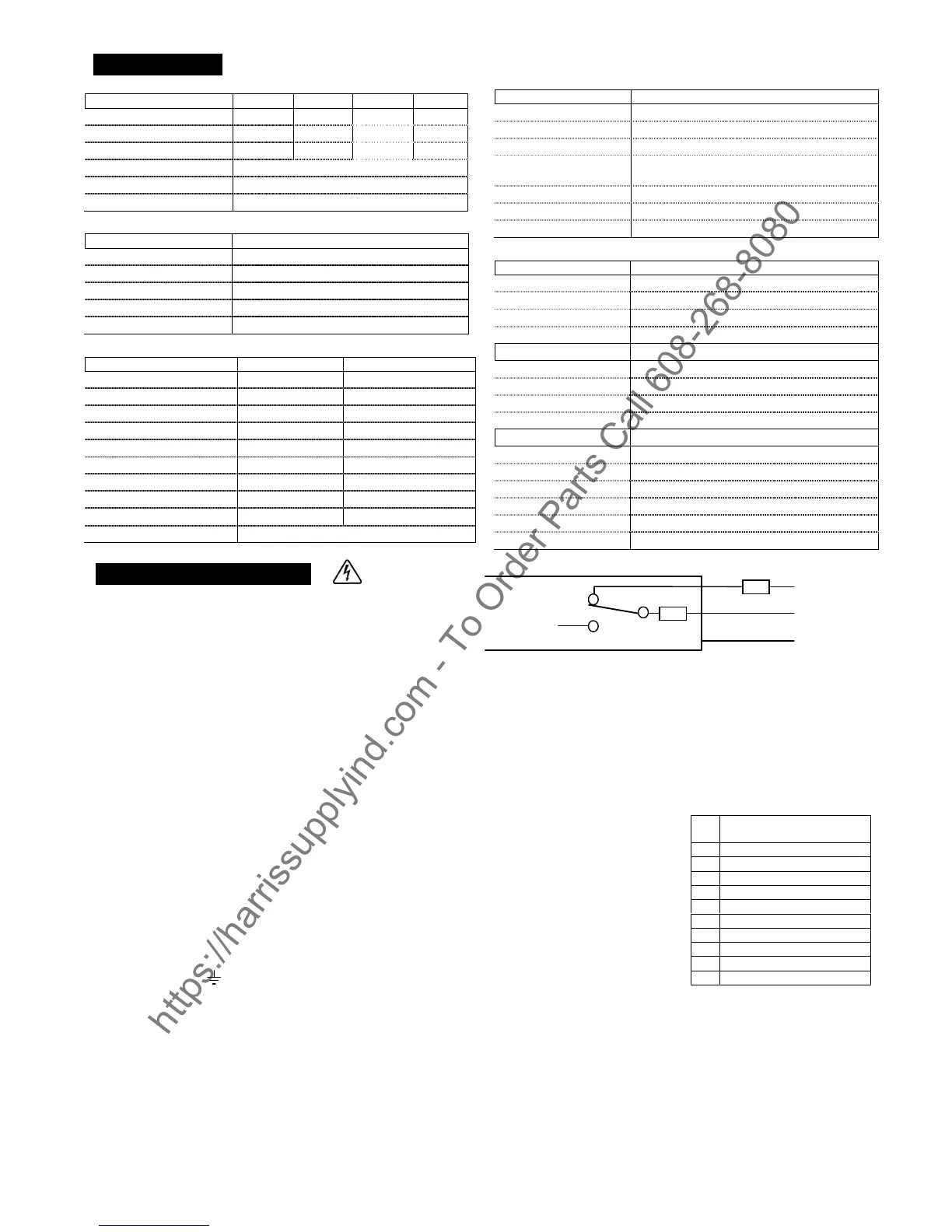
3) DC Battery Connection Procedure:
a) The green wire outputs battery voltage when the charger is not
plugged into AC to provide an interlock function – see Fig. 1. If
used, a user-supplied 1A fast-blow external fuse must be
installed inline to prevent damage. Shorting or drawing
more than 1A may damage charger and void the warranty.
b) Securely fasten the black ring terminal from the charger to the
negative terminal ("-", "NEG", NEGATIVE") of the battery pack.
c) Check that the correct charge algorithm is being used – refer to
section 4). Securely fasten the red ring terminal to the positive
terminal ("+", "POS", "POSITIVE") of the battery pack.
4) Check / Change Charging Algorithm:
The charger comes pre-loaded with algorithms for batteries as detailed in Table
1. If your specific battery model is not listed, please contact Delta-Q.
Each time AC power is applied with the battery pack NOT connected, the
charger enters an algorithm select/display mode for approximately 11 seconds.
During this time, the current Algorithm # is indicated on the ‘80%’ LED (Models
912-xx0x) or on the single LED (Models 912-xx1x). A single digit Algorithm # is
indicated by the number of blinks separated by a pause. A two digit Algorithm #
is indicated by the number of blinks for the first digit followed by a short pause,
then the number of blinks for the second digit followed by a longer pause.
To check / change the charging algorithm:
a) Disconnect the charger positive
connector from battery pack. Apply AC
power and after the LED test, the
Algorithm # will display for 11 seconds.
b) To change algorithm, touch positive
connector during the 11 second display
period to the battery pack’s positive
terminal for 3 seconds and then remove
– the Algorithm # will advance after 3
seconds. Repeat until desired Algorithm
# is displayed. A 30 second timeout is
extended for every increment.
Incrementing beyond the last Algorithm
moves back to the first Algorithm.
After desired Algorithm # is displayed,
touch the charger connector to the battery positive until the output relay is
heard to click (~10 seconds) – algorithm is now in permanent memory.
c) Remove AC power from the charger and reconnect the charger positive
connector to the battery pack. It is highly recommended to check a newly
changed algorithm by repeating step 4) above.
Product warranty is two years
please contact dealer of original equipment for warranty
service.
Note: This is a Class A product. In a domestic environment this product may cause radio
interference, in which case the user may be required to take adequate measures.
July 2006 © Delta-Q Technologies Corp. All rights reserved. PN: 710-xxxx Rev 1 V1.16
Alg
#
Battery Type
43 Discover AGM
27 Crown CR-325
21 Exide Flooded
12 Exide/Sonnenschein Gel
7 J305 DV/DT CP
6 DEKA 8G31 Gel
5 Trojan 30/31XHS
4 US Battery USB2200
3 T105 DV/DT CP
1 Trojan T105
Table 1.
B+
Charger
Internal
Output
NC
NO
GRN
B-
1A
https://harrissupplyind.com - To Order Parts Call 608-268-8080
 Loading...