Do you have a question about the Delta Tau PMAC and is the answer not in the manual?
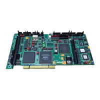
Description of what the PMAC Mini PCI offers.
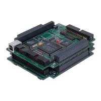
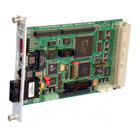
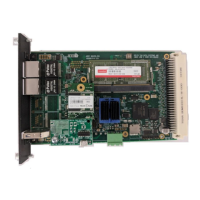
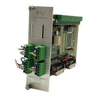
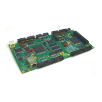
Physical size and layout of the PMAC Mini PCI.
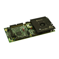
Describes initial setup and options for the hardware.
Details of the standard PMAC Mini PCI configuration.
Explains the DPRAM feature for high-speed communication.
Lists different CPU speed configurations available.
Describes specialized servo firmware for difficult systems.
Describes lookahead firmware for sophisticated path execution.
Describes an option for a more accurate clock crystal.
Describes user-specified firmware version option.
Describes the voltage-to-frequency converter option.
Describes the JOPTO port's I/O capabilities.
Explains jumpers related to power supply configuration.
Explains jumpers for setting clock frequencies.
Explains jumpers for encoder sample clock frequency.
Explains jumpers for DAC/ADC clock frequency.
Details jumper configurations for encoder types.
Details setup for single-ended encoders.
Details setup for differential encoders.
Describes jumpers for board reset and saving configurations.
Explains jumpers for serial communication settings.
Jumpers reserved for future use.
Explains jumpers for I/O configuration.
Describes resistor packs for termination.
Explains the optional DPRAM feature.
Describes the status LEDs on the board.
Describes the mapping of I/O signals.
Specific mapping for J3 outputs.
Specific mapping for J5 inputs.
Specific mapping for J5 outputs.
Dedicated use of Y:$FFC5 signals.
Dedicated use of Y:$FFC6 signals.
Describes the E0 jumper, reserved for future use.
Explains jumpers E1 and E2 for configuring output supply.
Explains jumpers E3-E6 for servo clock frequency.
Explains jumper E7 for input sourcing/sinking.
Describes jumpers E8-E10 for PMAC synchronization.
Explains jumpers E10A-E10C for flash bank selection.
Explains jumpers E11-E14 for encoder type selection.
Explains jumpers for amplifier control polarity.
Explains jumper E19 for disabling the watchdog timer.
Explains jumpers E20-E22 for flash bank selection.
Explains jumper E23 for firmware loading.
Explains jumpers E29-E33A for phase clock frequency.
Explains jumpers E34A-E37 for encoder sampling clock.
Explains jumpers E44-E47 for communication control.
Describes jumper E48, reserved for future use.
Explains jumper E49 for serial parity.
Explains jumper E50 for EAROM save.
Explains jumper E51 for power-up behavior.
Explains jumpers E85, E87, E88 for analog power configuration.
Explains jumper E89 for pull-up enable.
Explains jumper E90 for pull-up enable.
Explains jumper E98 for DAC/ADC clock.
Explains jumpers E101-E102 for amplifier output configuration.
Explains jumpers E110-E115 for V/F converter configuration.
Explains jumpers E116-E119 for V/F converter configuration.
Lists mating connectors for the J1 Display Port.
Lists mating connectors for the J2 Expansion Port.
Lists mating connectors for the J3 Multiplexer Port.
Lists mating connectors for the J4 Serial Port.
Lists mating connectors for the J5 OPTO I/O Port.
Lists mating connectors for the J7 A-D Inputs.
Lists mating connectors for the J8 Auxiliary I/O Port.
Lists mating connectors for the J11 Machine Connector.
Lists mating connectors for the TB1 Terminal Block.
General information about header connectors.
Detailed pinout for the J1 JDISP header.
Detailed pinout for the J3 JTHW header.
Detailed pinout for the J4 JRS232 header.
Detailed pinout for the J5 JOPT connector.
Detailed pinout for the J7 JS1 header.
Detailed pinout for the J8 JAUX header.
Detailed pinout for the TB1 Terminal Block.
| Category | Motion Controller |
|---|---|
| Type | Programmable Multi-Axis Controller |
| I/O Capability | Digital I/O, Analog I/O, PWM Outputs |
| Axes Supported | Up to 32 |
| Communication Interfaces | Ethernet, RS-232, USB |
| Feedback Devices Supported | Encoders, resolvers |
| Power Supply | 24V DC |
| Operating Temperature | 0°C to 50°C (typical) |
| Clock Speed | Varies by model (e.g., 100 MHz to 1 GHz) |
| Memory | Varies by model (e.g., 32 MB to 512 MB) |
| Flash Memory | Varies by model (e.g., 8 MB to 64 MB) |
| Operating System | Proprietary Real-Time OS |