6
ADJUSTING GUIDE BAR
TO TABLE SLOT
CAUTION: DISCONNECT MACHINE FROM POWER
SOURCE.
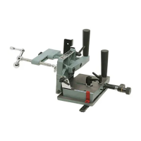
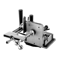
1. The tenoning jig is furnished with an adjustable guide
bar (A) Fig. 12, which allows the jig to be custom-fit to
your saw, eliminating any side-to-side play. Also, there is
a T-slot washer (B) on each end of the guide bar (A) to
keep the tenoning jig from lifting during operation.
NOTE: T-slot washers (B) need to be removed if your
table saw is not equipped with T-slotted miter gage slots.
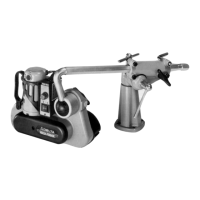
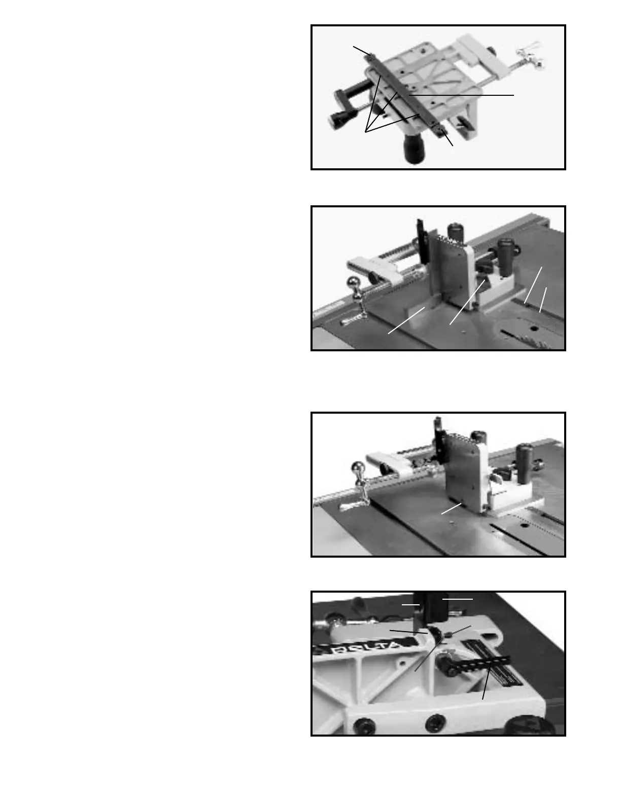
2. Place tenoning jig guide bar (A) Fig. 13, into left miter
slot (D) of machine as shown and slide miter gage back
and forth to determine if there is any side-to-side play. If
there is no side-to-side play and the tenoning jig slides
easily through the miter slot of the machine, no
adjustment is necessary; however, if the tenoning jig fits
too snugly, or if there is excessive play between the
guide bar (A), and miter slot (D) of the machine, proceed
as follows:
3. Remove tenoning jig from machine and place it
upside down as shown in Fig. 12.
4. Using the 2.5mm allen wrench (not shown) adjust
screws (C) Fig. 12, clockwise to eliminate play, or
counter-clockwise to provide a looser fit between the
guide bar (A) Fig. 13, and miter slot (D). Then insert the
tenoning jig back into the miter slot of the machine and
determine that fit is suitable, or if further adjustments are
required.
Fig. 12
Fig. 13
ALIGNING TENONING JIG
CAUTION: DISCONNECT MACHINE FROM POWER
SOURCE.
1. Place the tenoning jig guide bar (A) Fig. 13, into the
left miter gage slot.
2. Using a square (E) Fig. 13, check to see if the vertical
work support plate (F) is 90 degrees to the saw table. If
an adjustment is necessary, loosen lock handle (G),
move vertical work support plate (F) until it is 90 degrees
to the table and tighten lock handle (G).
3. With the vertical work support plate (F) Fig. 14,
adjusted at 90 degrees to the table, tighten set screw (H)
until it bottoms. This positive stop set screw (H) enables
you to rapidly position the vertical work support (F) 90
degrees to the table after it has been tilted.
4. The tenoning jig features a positive stop to ensure
fast and accurate positioning of the backstop (G) Fig. 15,
at 90 degrees to the saw table. To check and adjust the
positive stop at 90 degrees, loosen lock knob (H) Fig. 15,
and place one end of a combination square (J) on the
saw table and the other end against backstop (G). Check
to see if the backstop is at 90 degrees to the saw table.
If an adjustment is necessary, loosen locknut (K) Fig. 15,
and adjust screw (L) until head of screw contacts the
casting on vertical plate (M) at 90 degrees. Tighten
locknut (K) and lock knob (H) after adjustment is made.
Fig. 14
Fig. 15
A
B
B
C
D
A
G
E
F
F
H
H
K
L
M
J
G
 Loading...