12
5 Wired Controller and Wireless
Controller
5.1 Wired Controller
SPEED
AUTO
ROOM TEMP
SWING
HOUR
SET TEMP
MELT
1
2
3
4
5
6
7
8
9
10
11
12
13
14
15
16
MODE
FAN
SWING
TIMER
ON/OFF
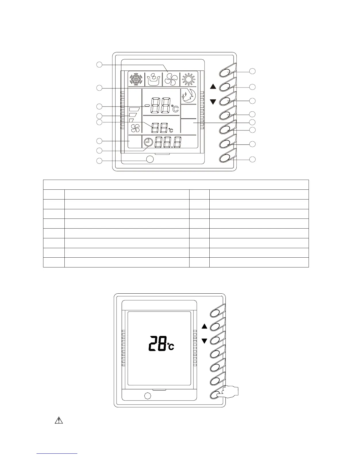
Fig. 8
Every Part of the Wired Remote Controller
1 Operating mode display (Cool, Dry, Fan, Heat) 9 On/Off button
2 Sleep mode display 10 Timer button
3 Environmental temp. display /Malfunction display 11 Sleep button
4 Fan control display (automatic, high, media, low) 12 Swing display
5 Set Temp. display 13 Fan control button
6 Defrosting display 14 Temp./ Timer decrease button
7 Timer display 15 Temp./ Timer increase button
8 Signal receiver 16 Mode button
ƹ
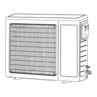
On/Off (Fig. 9)
When pressing the ON/OFF button, the unit will start.
When pressing the ON/OFF button again, the unit will stop.
SWING
ON/O FF
TIMER
FAN
MODE
Fig. 9
Note: The display in Fig. 2 is the turn-off state after the power supply is applied. When the
power supply is applied and the communication is normal, the environmental temperature will be