7
AG9032 v1 Spine and Leaf Switch
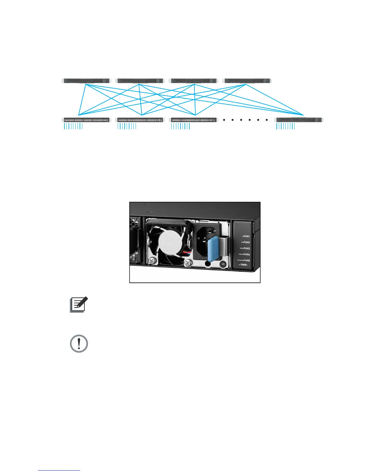
2.4 Data Center Deployment
The following gure illustrates the converaged Ethernet data center deployment.
Spine
Leaf
6x100G uplink
25G downlink via
Breakout cable
AG5648
25G downlink
1357911
246810 12
13 15 17 19 21 23
14 16 18 20 22 24
25 27 29 31 33 35
26 28 30 32 34 36
37 39 41 43 45 47
38 40 42 44 46 48 49 50
51 52
CONSOLE
PWR1PWR2 SYSTEMFAN
MGMT
AG7448
AG5648
25G downlink
1357911
246810 12
13 15 17 19 21 23
14 16 18 20 22 24
25 27 29 31 33 35
26 28 30 32 34 36
37 39 41 43 45 47
38 40 42 44 46 48 49 50
51 52
CONSOLE
PWR1PWR2 SYSTEMFAN
MGMT
AG7448
AG5648
25G downlink
1357911
246810 12
13 15 17 19 21 23
14 16 18 20 22 24
25 27 29 31 33 35
26 28 30 32 34 36
37 39 41 43 45 47
38 40 42 44 46 48 49 50
51 52
CONSOLE
PWR1PWR2 SYSTEMFAN
MGMT
AG7448
AG9032 v1 AG9032 v1 AG9032 v1 AG9032 v1
AG9032 v1
(Figure 2-5: Converaged Ethernet Data Center Deployment)
2.5 Power Supply Modules
The power supply modules are hot-swappable power supply units (PSUs) for the switch.
You can install up to two PSUs. The PSUs operate in a load-sharing mode and provides 1+1
redundancy.
(Figure 2-6: Power Supply Unit)
NOTE:
1+1 redundancy is a system where a switch power supply is backed up by
another switch power supply in a load-sharing mode. If one power supply fails,
the other power supply takes over the full load of the switch.
WARNING:
• The switch includes plug-in power supply and fan tray modules that are
installed into its chassis. All modules have a front-to-back airow direction.
• Risk of explosion if battery is replaced by an incorrect type. Dispose of used
batteries according to the instructions.
• Remove the power cable from the module prior to removing the module
itself. Power cable must not be connected prior to insertion in the chassis or
equivalent.