15
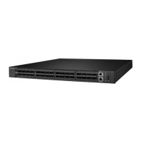
AG9032 v1 Spine and Leaf Switch
Chapter 4: Making the Network Connections
The AG9032 v1 switch is designed to provide high-speed, lossless Ethernet connections
between server racks through its 100G QSFP ports. This chapter describes how to make
network connections to the switch.
4.1 Twisted-pair Connections
The switch’s Management port connection requires an unshielded twisted-pair (UTP)
cable with RJ-45 connectors at both ends. Use Category 5, 5e or 6 cable for 1000BASE-T
connections, Category 5 or better for 100BASE-TX connections, and Category 3 or better for
10BASE-T connections.
4.1.1 Cabling Guidelines
The RJ-45 port on the switch supports an automatic MDI/MDI-X pinout conguration, so
you can use a standard straight-through twisted-pair cable to connect to any other network
device (PCs, servers, switches, routers, or hubs).
4.1.2 Connecting to the Management Port
1. Attach one end of a twisted-pair cable segment to the link device’s RJ-45 connector.
RJ-45 connector
(Figure 4-1: Making a Connection to the Management Port)
2. Attach the other end to the Management port on the switch.
Make sure the twisted pair cable does not exceed 100 meters (328 ft) in length.
3. When the connection is made, the Mgmt LED (on the switch) will light green to indicate that
the connection is valid.