4
• Appearance and MechanismChapter 2
2.2 LED Identification
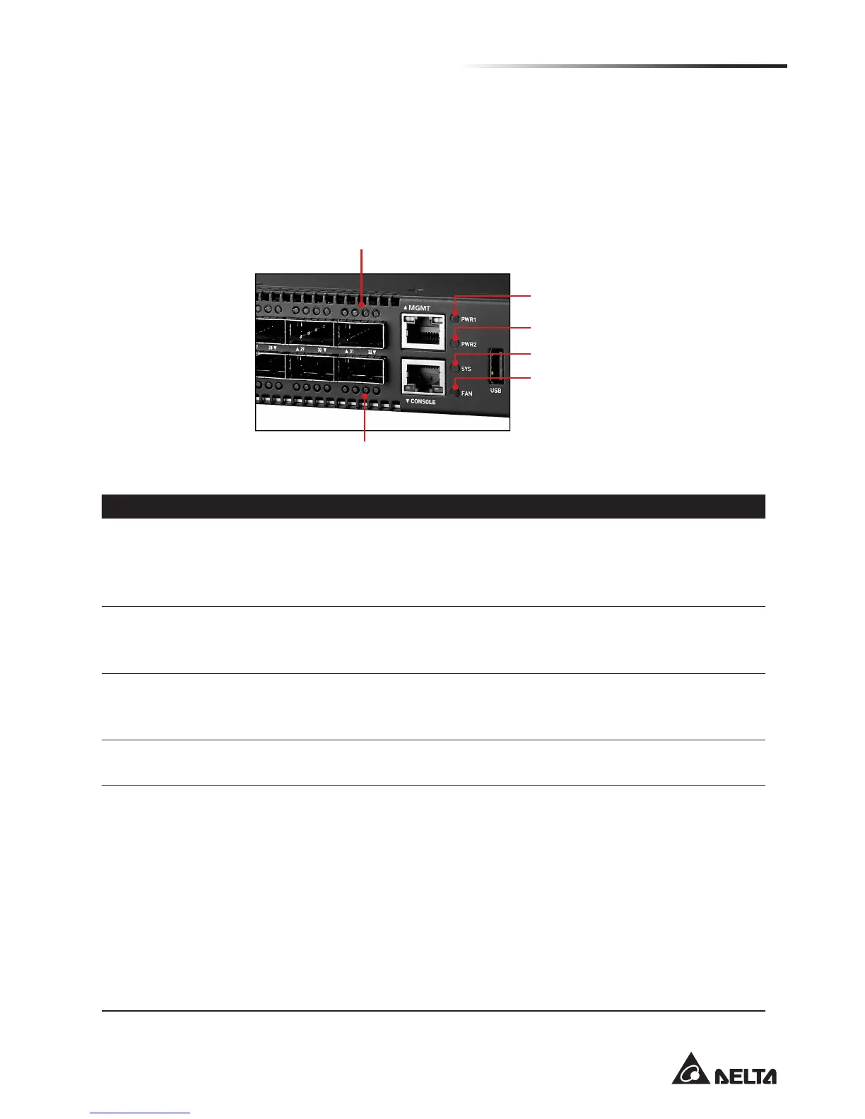
This section provides an overview of the front and rear LEDs.
2.2.1 Front LEDs
Upper QSFP28 Port LED
Lower QSFP28 Port LED
Power 1 LED
Power 2 LED
System LED
Fan LED
(Figure 2-3: Front LED Identification)
LED Description
System LED
• Off – Power is off
• Solid Green – Normal operation
• Blinking Green – Booting
• Solid Red – Critical Alarm
Power 1 LED
• Solid Green – Power Supply 1 is supplied to the switch & operating normally
• Blinking Amber – Power Supply 1 is failed
• Off – Power is disconnected
Power 2 LED
• Solid Green – Power Supply 2 is supplied to the switch & operating normally
• Blinking Amber – Power Supply 2 is failed
• Off – Power is disconnected
Fan LED
• Solid Green – FAN operating normally
• Solid Amber – A FAN is failed
100G QSFP28
slots
(Four LEDs
per port)
LED1
• Off – No link
• Solid Green – A valid 100Gbps link (4x25G)
• Solid Amber – A valid 40Gbps link (4x10G)
• Solid Blue – A valid 25Gbps link
• Solid Purple – A valid 10Gbps link
LED 2-4 (working in breakout)
• Off – 40/100G operation (assuming LED1 is illuminated) or No link
• Solid Blue – A valid 25Gbps link
• Solid Purple – A valid 10Gbps link