User and Installation Manual, DE212 GLOBAL
DELTA RC AS Page 17 of 36
Document 02743
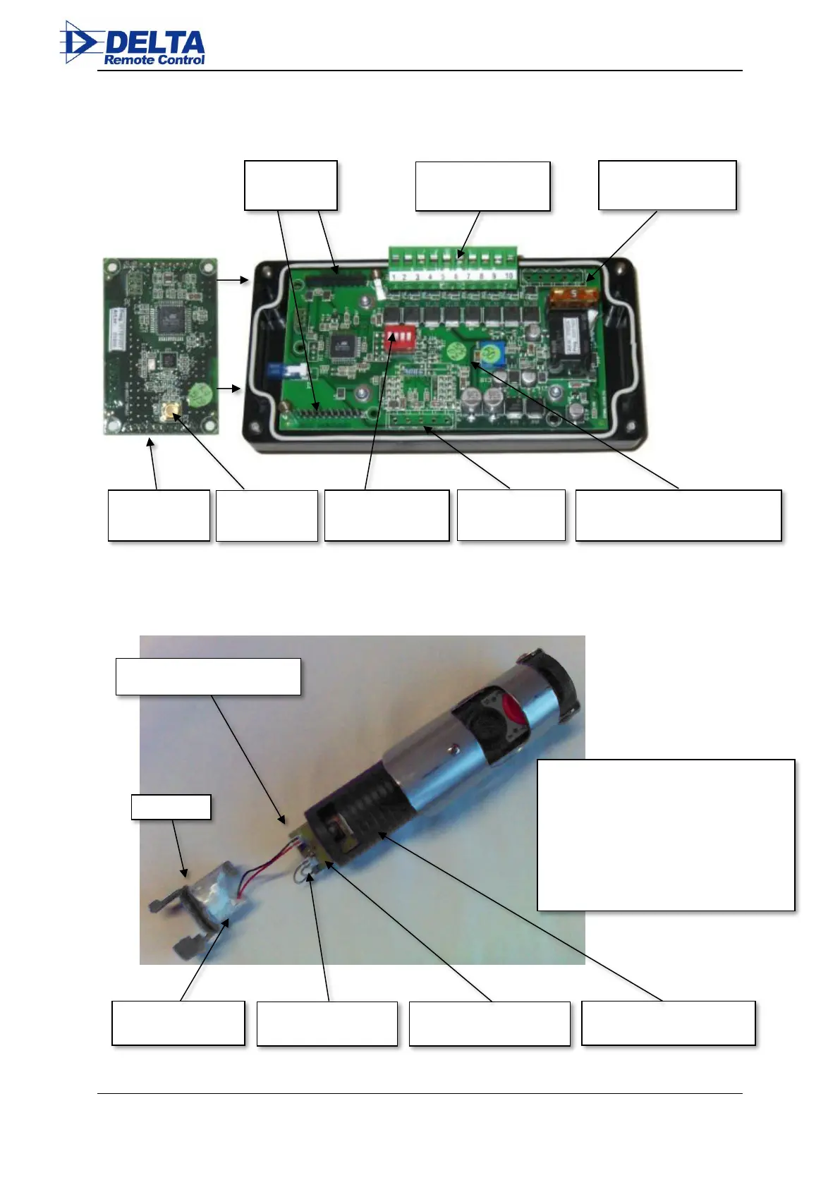
5.3.1 Receiver front unit, parts identification
5.3.2 Transmitter parts identification
Printed Circuit Board,
#01855
Battery module connector, P3
Transmitter housing
#02704
Battery and charge connector
connected.
Printed circuit board shown partly inserted in
the housing.
During assembly, carefully make sure the O-
ring and wires are not jammed
between the battery module and housing.
Double-check polarity!
Main printed circuit board
 Loading...