EasyManua.ls Logo

Delta DE212 GLOBAL - Receiver Unit Connections

Delta DE212 GLOBAL
36 pages
Print Icon
To Next Page IconTo Next Page
To Previous Page IconTo Previous Page
Loading...
User and Installation Manual, DE212 GLOBAL
DELTA RC AS Page 5 of 36
Document 02743
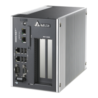
2.2 RECEIVER UNIT CONNECTIONS
All connections to the Deadman system are made in the receiver unit.
Receiver connections
In order to get the most stable range between the receiver and the handheld transmitter, it is
recommended to install an antenna at the outside of the refuelling truck cabin. With an external
antenna the path between the two units is less dependent on radio shielding from the driver’s cabin
walls and items between the two units.
Antenna connection
HF-module
1. Timer Beeper output
2. Timer Warning output
3. Extra function
4. Deadman output
5. STOP
6. Interlock
7. Minus-pole for input voltage (-)
8. Plus-pole for input voltage (+)
9. Do not connect
10. DP Reset/Override
Receiver main board
1
2
3
4
5
6
7
8
9
10
Receiver connector P1
Input voltage fuse, 5A auto fuse
5
4
3
2
1
Receiver connector P3
1. External override
2. DP Switch
3. External STOP
4. Not in use
5. GND
SW2, Function select
(See chapter 3.3)
1
2
3
4
1
2
3
4
5
1. Do not connect
2. Do not connect
3. GND
4. DP Output
5. DP Warning Light
Receiver connector P2

Related product manuals