Do you have a question about the Delta DT4848 and is the answer not in the manual?
Warnings and precautions to prevent electric shock during operation and maintenance.
Advises on using the controller in suitable environments and potential dangers.
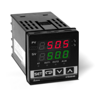
Identifies and explains the function of the controller's display, LEDs, and buttons.
Lists DTB series models and their corresponding panel dimensions (W×H).
Details selections for output groups and optional features like EVENT inputs and CT.
Details input voltage, power, memory, display, sensor types, control modes, and outputs.
Lists register values and temperature ranges for various analog and RTD/Thermocouple sensors.
Explains the three operation modes and how to navigate between them using keys.
Describes the process of selecting desired functions and changing settings using navigation keys.
Details parameters for heating/cooling control cycles, dual loop output, and valve feedback.
Explains settings related to valve feedback, dead band, and regulation for valve control.
Explains selection of heating, cooling, or dual loop control based on output group configuration.
Details PID mode selection (n=0~4) and parameter settings like Proportion Band and Ti.
Covers editing patterns and steps for PID program control, including set point and time.
Describes the setup of alarm outputs, covering set values, alarm types, and operation logic.
Explains deviation, absolute value, and reverse deviation alarm types and their conditions.
Explains the CT function for current measurement and EVENT inputs for RUN/STOP and setting switch.
Describes PID program control, patterns, steps, link patterns, and cycle parameters.
Details how to execute PID programs, manage steps, and interpret the display.
Explains the selection of PID parameter groups and storage of AT values.
Details settings for valve control, including feedback and auto-tuning.
Covers supported transmission speeds, formats, protocols, and function codes for RS-485.
Lists addresses and content for reading/writing process values, set points, and control parameters.
Details addresses for communication write selection, unit display, decimal point, and AT settings.
Provides cutout dimensions in millimeters for DTB4824, DTB4848, and DTB4896 models.
Identifies terminals for DTB4824, DTB4848 (with/without EVENT/CT), and DTB4896/DTB9696.
Provides external dimension drawings for DTB4824, DTB4848, DTB4896, and DTB9696 models.
Instructions for panel cutout installation using mounting brackets and CT wiring.
Step-by-step guide for inserting and securing the mounting bracket to the controller.
Table of communication error codes, PV read back values, and their meanings.
Explains normal and error display messages for PV, SV, and EEPROM status.
Provides contact addresses, phone, and fax numbers for Delta offices in Asia, North/South America, and Europe.
| Brand | Delta |
|---|---|
| Model | DT4848 |
| Category | Temperature Controller |
| Language | English |