Do you have a question about the Delta DTB4824 and is the answer not in the manual?
Critical warnings to prevent electric shock.
Risks associated with open-type controller applications.
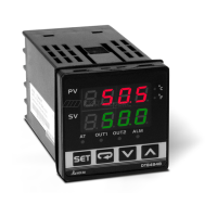
Explanation of PV and SV displays.
Descriptions of SET, Mode, Up, Down keys.
Meanings of AT, Output, Alarm, and Unit LEDs.
Overview of models, panel sizes, output groups, and optional functions.
Input voltage, power, temp, humidity, altitude.
Display, sensors, control modes, outputs, communication.
Vibration, shock resistance.
Maps sensor types to register values and temperature ranges.
Details on modes and how to set parameters.
Functions of PV/SV display, SET, Up, Down keys.
Settings for PID, alarms, input type, and control mode.
Settings for dual loop, valve control, and feedback.
Analog output regulation and alarm configurations.
Settings for communication format, address, baud rate, etc.
Selecting PID modes and configuring band, Ti, Td, deviation.
Editing pattern numbers, step temperatures, and times.
Setting execution cycles and understanding program display.
Choosing heating, cooling, or dual loop control action.
Locks all parameters and temperature settings.
Locks settings except for the Set Point (SV) value.
Describes 8 types of alarm outputs based on deviation or absolute values.
Alarms for deviation above/below set point, with standby.
Hysteresis and CT-based alarm outputs.
Using EVENT1 for RUN/STOP and EVENT2 for setting switching.
Explains patterns, steps, and program control logic.
Setting start pattern, steps, execution time, and links.
Selecting PID groups and setting P, I, D values.
Corresponds SV values to selected PID parameters.
Settings for valve control, feedback, timing, and dead band.
Details on RS-485 protocol, speed, and register addresses for parameters.
Comprehensive list of RS-485 registers for various settings and statuses.
Visual identification of panel cutouts and terminal connections for different models.
Visual representations of external dimensions for DTB4824, DTB4848, DTB9696, DTB9696RRV.
Instructions for panel mounting, bracket installation, and CT wiring.
Comprehensive guide to communication error codes and display messages.
Contact information for Delta Electronics in Asia, Americas, and Europe.
| Mounting | Panel Mount |
|---|---|
| Control Output | Relay |
| Output 1 | Relay |
| Input Type | Thermocouple, RTD, Analog |
| Display | Dual, 7-segment LED |
| Dimensions | 48mm x 48mm x 77mm |
| Control Mode | PID, On/Off |
| Control Method | PID |