Do you have a question about the Delta DTK Series and is the answer not in the manual?
Safety warnings for electrical shock, installation environment, and proper wiring.
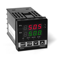
Description of the controller's display indicators, LEDs, and function buttons.
Details on controller series, panel sizes, output, and communication options.
Summary of electrical, sensor, control, and environmental specifications.
Settings for RUN/STOP, alarms, outputs, and other operational parameters.
Parameters for input type, temperature units, control modes, and communication setup.
Parameters for auto-tuning, PID, hysteresis, filters, and output adjustments.
Guide to sensor selection and configuring display units.
Setting input value limits, digital filters, and linear compensation.
Compensating analog outputs and checking firmware version.
Configuring output control, dead band, and control modes.
Auto-tuning, limiting output range, and temperature range settings.
Restoring factory settings and managing panel key lock.
Configuring various alarm types, delays, and advanced settings.
Configuring RS-485, using commands, and CRC check.
Physical cutout dimensions and wiring configurations.
The Delta DTK Series Temperature Controller is an open-type device designed for precise temperature regulation. It is crucial to exercise caution during installation and operation, particularly regarding electrical safety. Users are warned against touching AC terminals when power is supplied and must ensure power is disconnected before internal checks. The controller is not intended for applications where serious human injury or property damage could occur without additional safety evaluations.
The DTK Series Temperature Controller manages temperature through various control modes, including PID, manual, and ON/OFF. It features a clear LCD display for both the Process Value (PV) in red and the Set Point (SV) in green. The device supports a wide range of temperature sensors, including various thermocouple types (K, J, T, E, N, R, S, B, L, U, TXK), 3-wire Platinum RTDs (Pt100, JPt100), and resistance sensors (Cu50, Ni120).
It offers multiple output options: relay output (250 VAC, 8A), voltage pulse output (12VDC +/-15%), and DC current output (4-20 mA). The controller can be configured for single or dual alarm outputs, with various alarm modes such as deviation upper/lower limit, absolute value upper/lower limit, and hysteresis alarms. Communication is supported via RS485, allowing for remote monitoring and control.
The device includes an auto-tuning function for automatic generation of PID parameters, simplifying setup and optimizing control performance. It also allows for digital filtering and linear compensation of input signals to enhance display stability and accuracy. Analog output compensation is available for fine-tuning current output signals.
The controller operates in three main modes: operation, regulation, and initial setting, accessible via the SET key.
Key features include:
| Brand | Delta |
|---|---|
| Model | DTK Series |
| Category | Temperature Controller |
| Language | English |