10
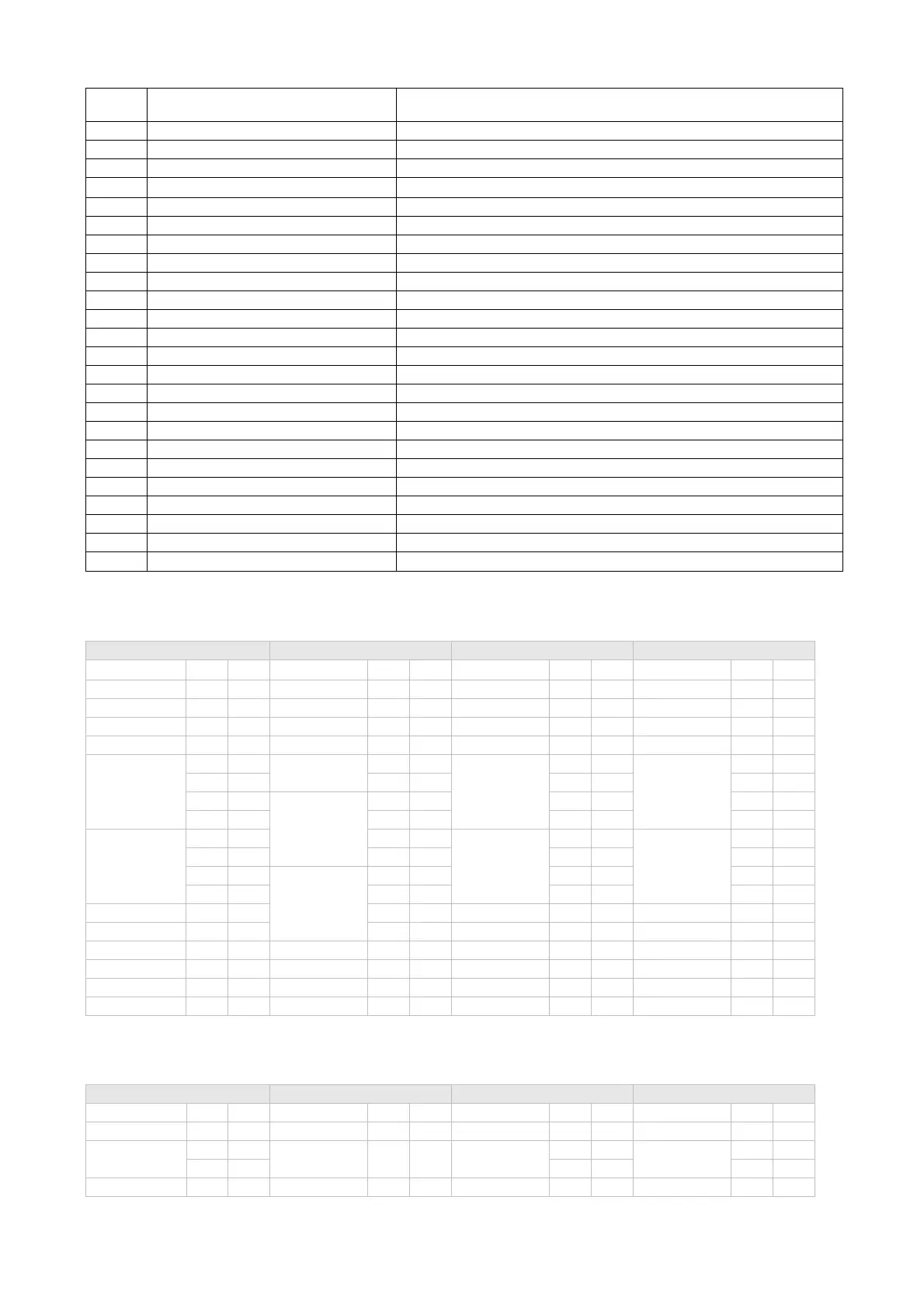
100FH
The setting of Dead Band when Dual Loop
output controls are used.
-999 ~ 9999
1010H Hysteresis setting of the 1st output group 0~9999
1011H Hysteresis setting of the 2nd output group 0~9999
1012H Read Output 1 amount Unit is 0.1%.
1013H Read Output 2 amount Unit is 0.1%.
1014H Write Output 1 amount Unit is 0.1%. Write operation is valid only under manual tuning mode.
1015H Write Output 2 amount Unit is 0.1%. Write operation is valid only under manual tuning mode.
1016H Temperature regulation value -99.9 ~ +99.9. Unit is 0.1.
1017H PV gain -0.999 ~ +0.999
1018H Control RUN/STOP setting 0: Stop, 1: Run (default)
101AH Set Button Status b0: Loop, b1: Up, b2: Set, b3: Down, 0: press down.
101BH Display decimal points 0: no decimal points, 1: one decimal point
101CH Selection of communication write-in 0: Disallow (default), 1: Allow
101EH Software version V1.00 indicated as 0x100
1020H Alarm 1 output mode Please refer to “Alarm Output Selection” for detail.
1021H Alarm 2 output mode Please refer to “Alarm Output Selection” for detail.
1022H AT setting 0: Stop (default), 1: Start
1023H Setting lock status 0: no locking; 1: full locking; 2: SV adjustible.
1024H Upper limit of alarm output 1 Please refer to “Alarm Outputs” for detail.
1025H Lower limit of alarm output 1 Please refer to “Alarm Outputs” for detail.
1026H Upper limit of alarm output 2 Please refer to “Alarm Outputs” for detail.
1027H Lower limit of alarm output 2 Please refer to “Alarm Outputs” for detail.
1028H Temperature Filter Range
Range of temperature filter: 10~1000, unit: 0.01 Ԩ, default: 100 (1.0 Ԩ)
1029H Temperature Filter Factor Setting range: 0~50, default: 8
102AH Read LED Status
b1: ALM2, b2: Ԩ, b3: Ԭ, b4: ALM1, b5: OUT2, b6: OUT1, b7: AT
3. Format of Communication Transmission: Command Code, 03: read words, 06: write 1 word.
ASCII Mode
Read Command Read Command Response Write Command Write Command Response
STX
’:’ ’:’
STX
’:’’:’
STX
’:’’:’
STX
’:’ ’:’
ADR 1 ‘0’ ‘0’ ADR 1 ‘0’ ‘0’ ADR 1 ‘0’ ‘0’ ADR 1 ‘0’ ‘0’
ADR 0 ‘1’ ‘1’ ADR 0 ‘1’ ‘1’ ADR 0 ‘1’ ‘1’ ADR 0 ‘1’ ‘1’
CMD 1 ‘0’ ‘0’ CMD 1 ‘0’ ‘0’ CMD 1 ‘0’ ‘0’ CMD 1 ‘0’ ‘0’
CMD 0 ‘3’ ‘2’ CMD 0 ‘3’ ‘2’ CMD 0 ‘6’ ‘5’ CMD 0 ‘6’ ‘5’
Starting data
address
‘1’ ‘0’ Number of data
(count by byte)
‘0’ ‘0’
Starting data
address
‘1’ ‘0’
Starting data
address
‘1’ ‘0’
‘0’ ‘8’ ‘4’ ‘2’ ‘0’ ‘8’ ‘0’ ‘8’
‘0’ ‘1’ Start address
data
1000H/081xH
‘0’ ‘1’ ‘0’ ‘1’ ‘0’ ‘1’
‘0’ ‘0’ ‘1’ ‘7’ ‘1’ ‘0’ ‘1’ ‘0’
Number of data
(word/Bit)
‘0’ ‘0’ ‘F’ ‘0’
Data content
‘0’ ‘F’
Data content
‘0’ ‘F’
‘0’ ‘0’ ‘4’ ‘1’ ‘3’ ‘F’ ‘3’ ‘F’
‘0’ ‘0’
Address data
1001H
‘0’ ‘E’ ‘0’ ‘E’ ‘0’
‘2’ ‘9’ ‘0’ ‘8’ ‘0’ ‘8’ ‘0’
LRC 1 ‘E’ ‘D’ ‘0’ LRC1 ‘F’ ‘E’ LRC1 ‘F’ ‘E’
LRC 0 ‘A’ ‘C’ ‘0’ LRC 0 ‘D’ ‘3’ LRC 0 ‘D’ ‘3’
END 1 CR CR LRC 1 ‘0’ ‘E’ END 1 CR CR END 1 CR CR
END 0 LF LF LRC 0 ‘3’ ‘3’ END 0 LF LF END 0 LF LF
END 1 CR CR
END 0 LF LF
LRC checksum:
LRC check is the added sum from “Address” to “Data content”. For example: 01H + 03H + 10 + 00H + 00H + 02H = 16H. Then, take the
complementary of 2 to get EA.
RTU
Mode
Read Command Read Command Response Write Command Write Command Response
ADR 01H 01H ADR 01H 01H ADR 01H 01H ADR 01H 01H
CMD 03H 02H CMD 03H 02H CMD 06H 05H CMD 06H 05H
Starting data
address
10H 08H
Number of data
(count by byte)
04H 02H
Starting data
address
10H 08H
Starting data
address
10H 08H
00H 10H 01H 10H 01H 10H
Number of data 00H 00H
Start address
01H 17H Data content 03H FFH Data content 03H FFH
 Loading...


